Revit Application Macro

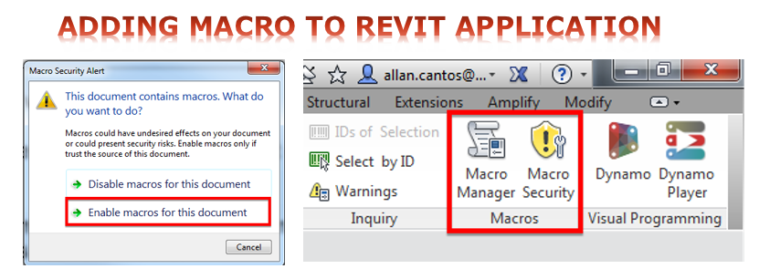
I came across ArchSmarter Toolbox where you can download a number of Revit Macro for free and one of my favourite so far amongst the list is the “Align Views”. Please watch this quick video tutorial from ArchSmarter to give you a basic understanding of Revit macro:

How to run a Revit macro

Adding one macro to your Revit application is clearly explained by the Founder of ArchSmarter Mr Michael Kilkelly HERE, but what if you have to combine two or more macros, how would you do that?

As you can see, we do not have any macro from “Application” tab and “Project1” tab.

Go ahead and download the Revit Macros that you like and transfer the first macro by following the video tutorial from the link provided above.

Please see below the sample of the macros I’ve added on my Revit Application.

Here is the test video for the Align Views macro: Test Video

Let me know by giving your comments below if you want to learn how to combine the three macros into a single application macro code and I am more than happy to create a separate article in discussing the process I did.

Have a great day.

Cheers,

Allan Cantos EngTech MICE

BSc. Civil Engineering / Principal Structural Technician

Pile Cut-off Level using Dynamo

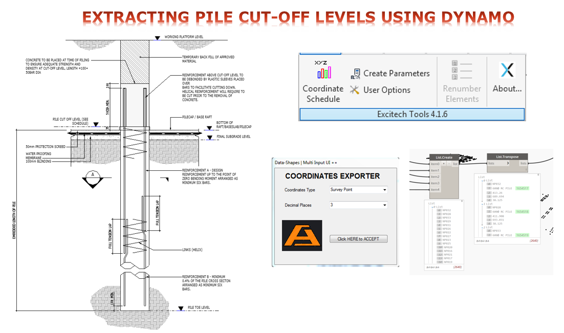
If you are following my post, previously, I looked at exporting the pile coordinates either from Survey Point or Project Base Point and explained in details where the results are coming from with the help of diagrams. If you missed that section, you better go back to that article first before continue reading this one.

Here is the link for that article: Exporting Pile Coordinate from Survey Point instead of Project Base Point

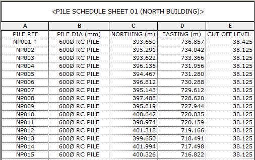
Today, I want to give an update to my Dynamo script; to include in my final output the “Pile cut-off level” values for each individual piles on my project.

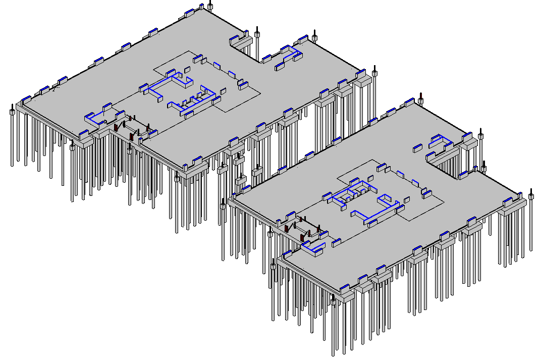
Here is the project that I’ll be looking at:


And I want to have the same result using the revised Dynamo script to one shown below.

Here is what the script looks like before from Exporting Pile Coordinate from Survey Point instead of Project Base Point:

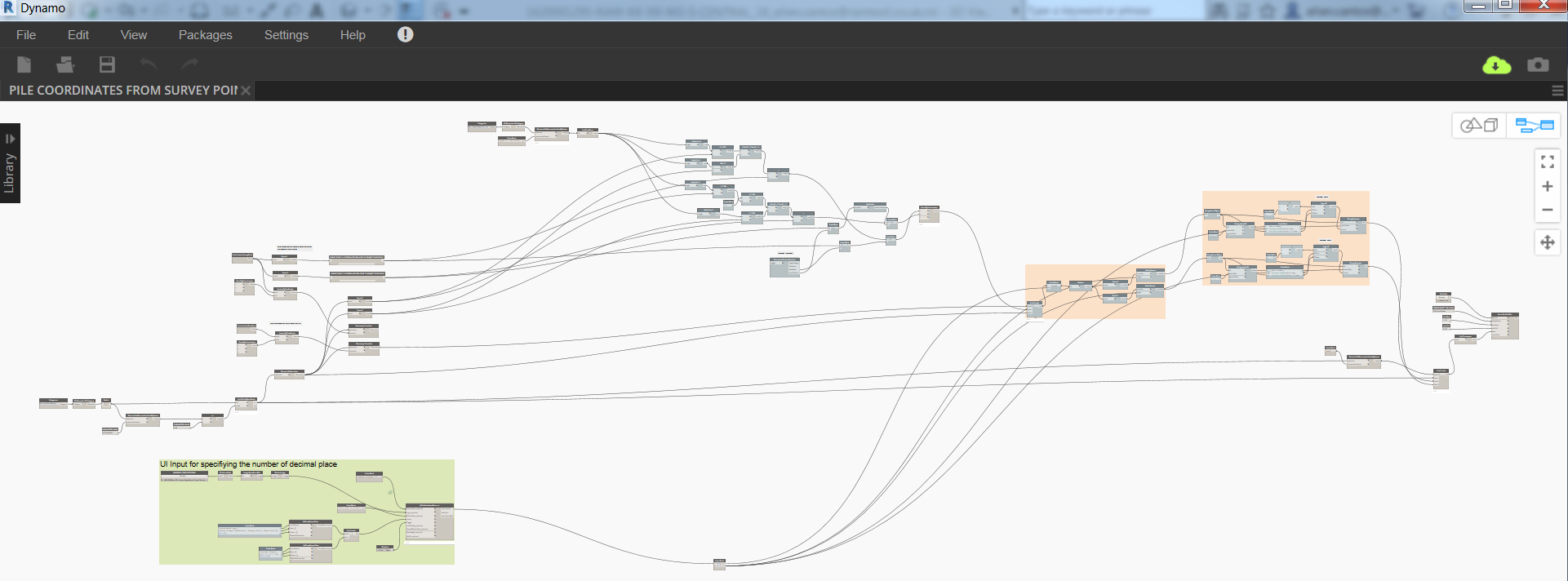
And here is it now after the upgrade:

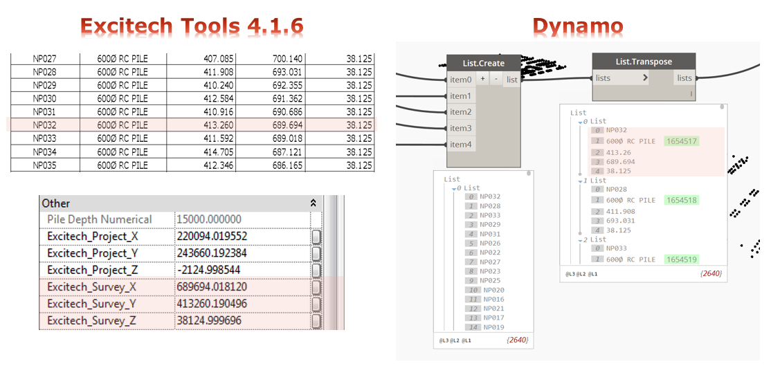
And the result when I “Run” the script and the comparison to Excitech Tools:

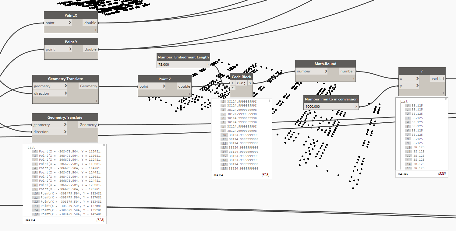
The first update I did was to extract the z-coordinates (Point.z node) and add 75mm (check this value with your structural engineer) for the “Embedment Length”, then round-up the result before converting the units from millimetres to meters. One thing that you need to make sure is that your pile is attached to the bottom of your pile cap. The 75mm embedment length calculation begins at the topmost level of the pile.

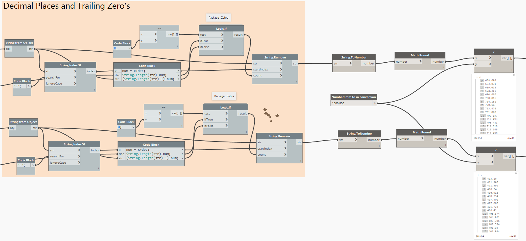
Another update I did was to convert the result from the “String.Remove” node to a number using the “String.ToNumber” node in order for me to convert the unit as well from millimetres to meters. As you may already know, the information provided by the “String.Remove” node is considered as a string and this is the reason why I need to convert it to a number first in order for the “Divide” node to work.

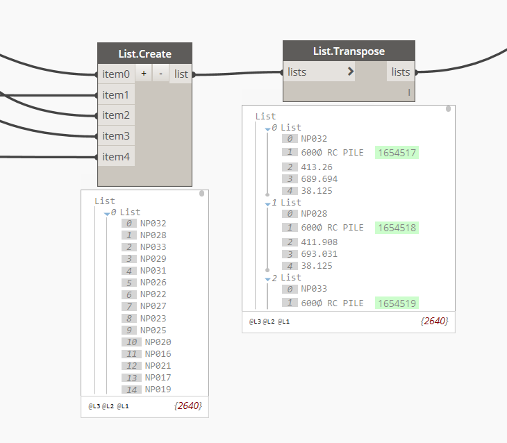
And finally, add a new item, item4, from List.Create node to include the pile cut-off level.

Now I am ready to assign this values to my Northing, Easting, and Pile Cut-off Level project parameters using my separate Dynamo script.

You can use this workflow if you don’t have Excitech Tools installed on your machine as part of your Revit Add-ins.

If you want to give it a try, please fill up a few details below and you will receive the download link.

    I welcome your comments, questions, corrections and additional information relating to this article. If you know a better way, please leave your comment, by all means, let me know. Thanks.

    Have a great day!

    Cheers,

    Allan Cantos EngTech MICE

    BSc. Civil Engineering / Principal Structural Technician


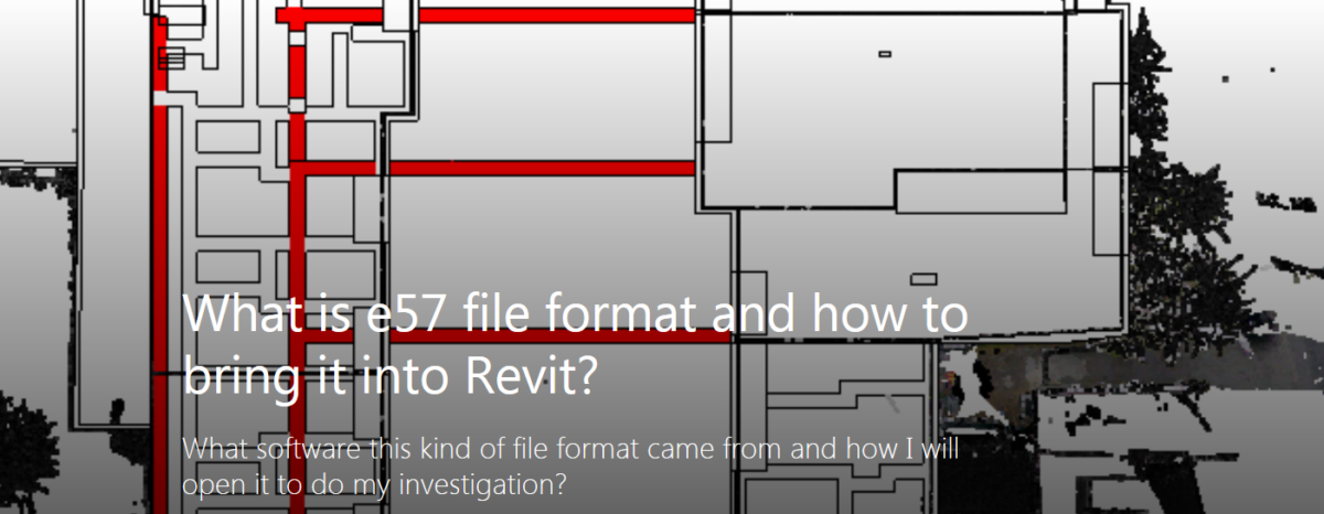
    What is e57 file format and how to bring it into Revit?

    An engineer came to me and asked me to investigate the file he received which was under e57 file format. Honestly, at first, I don’t know what software this kind of file format came from and how I will open it to do my investigation. Thanks to the internet, I went to Google and did a little bit of research about e57 file type.

    According to http://www.libe57.org/, the e57 file format is a compact, vendor-neutral format for storing point clouds, images, and metadata produced by 3D imaging systems, such as laser scanners. So, from here, I can conclude that the e57 file is something to do with point clouds. The file happens to be a survey information on existing structures.

    Now, the next question is, how I can bring this e57 file format to Revit? Will it land at the same coordinate system I have on my Revit model? What positioning I will use? For now, I don’t know the answer as this will be my first time to encounter e57 file format.
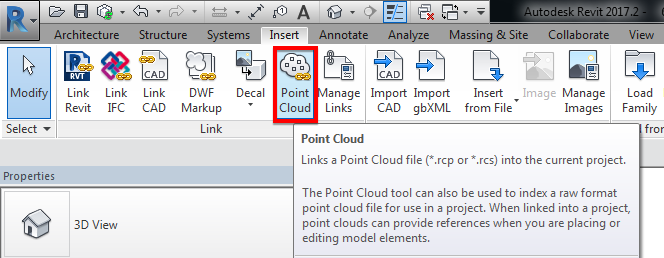
    Link the “Point Cloud” under “Insert” tab and “Link” menu ribbon options. I found out that you can link the e57 file format. See image below for file type options supported.

    Now, I’ll try to import the e57 file format using “Auto – Origin to Origin” positioning and see what will happen.
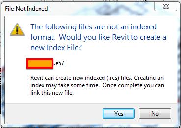
    I’ve got that warning message and from that, it leaves me no choice than to click “Yes” for it to work. So, I clicked “Yes” and this window popped up:
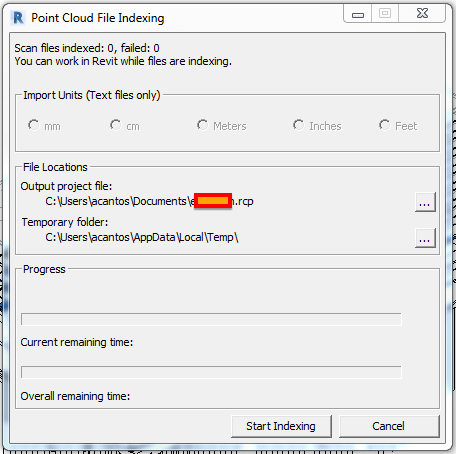
    Continue the process by clicking the “Start Indexing” button then you can grab a coffee as this will take a while depending on the size of your e57 file. In my case, the file size is around 30GB, so enormous!

    While the file indexing is progressing, you can do other stuff to keep you busy.
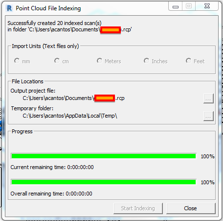
    Now the process is completed. Unfortunately, I lost track of the time it took to process the almost 30GB e57 file. However, I reckoned, it took 2.5 hours using my Lenovo ThinkPad P70 laptop. Additional specifications are shown below.

    As advised previously, we can link the new file once completed, which is now in the format of .rcp. A .rcp format file is a project file that groups together multiple .rcs scan files. The result of indexing a raw format file is a .rcp file and one or more .rcs files.

    For now, I’ll use “Auto – Origin to Origin” as positioning.
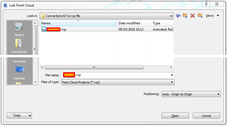
    Click “Open” and it gave me a warning.
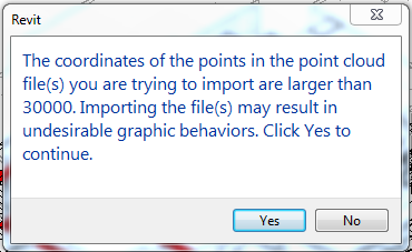
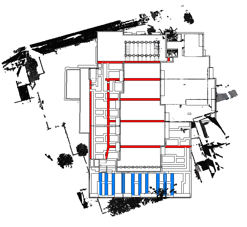
    I hit “No” and try again but, this time using “Auto – Center to Center” positioning, then click “Open”.
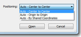
    I have the same warning as the one above. This time instead of clicking “No”, I hit the “Yes” button and the result…..the point cloud is rotated.
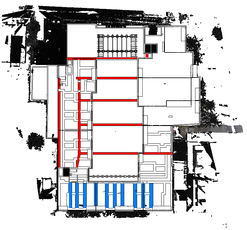
    I tried again but, this time using the last positioning option, which is “Auto – By Shared Coordinates”, then click “Open”.

    Again, same warning message, hit “Yes” and voila! it landed on the area around the building to be constructed.
    I welcome your comments, questions, corrections and additional information relating to this article. If you know a better way, please leave your comment, by all means, let me know. Thanks.

    Have a great day.

    Cheers.

    Allan Cantos EngTech MICE

    BSc Civil Engineering / Principal Structural Technician

    Positive SSL