Hi! How are you doing? I trust you are well.
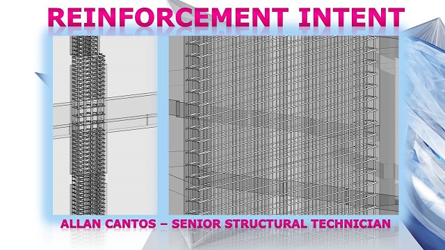
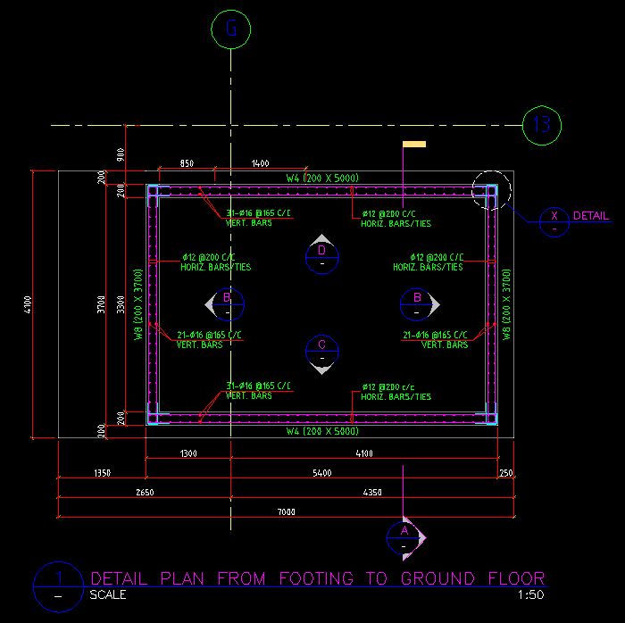
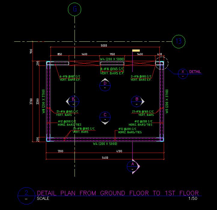
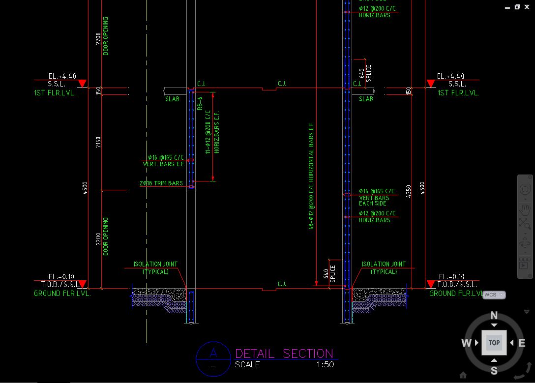
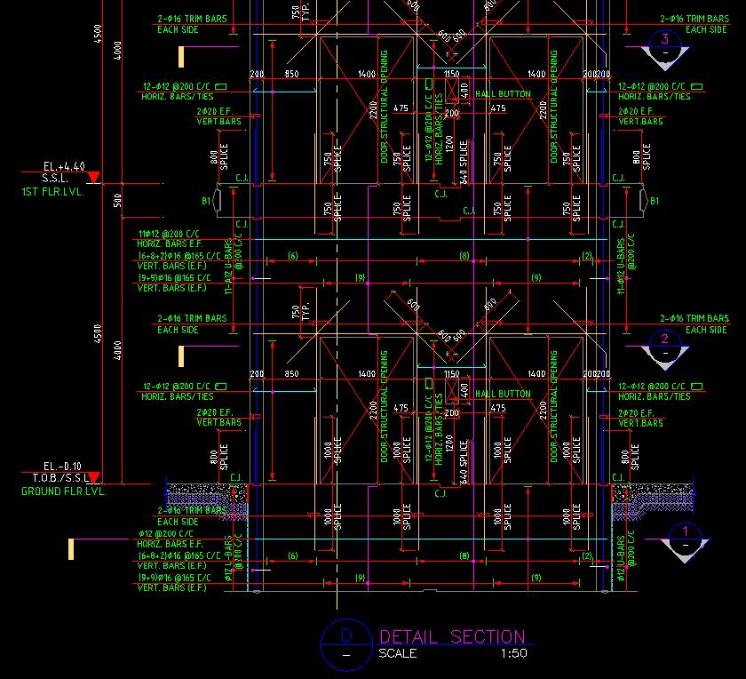
Today I’ll open a discussion for all Structural Technicians about how you normally create drawings for reinforcement intent using Revit. I believe each and every structural technician has their own view on how to create drawings to show the reinforcement intent. Many years ago, I worked in a contractor company where I provided very detailed information for reinforcement for each individual element. See few samples of shop drawings below which I’ve done in AutoCAD and Revit wasn’t available during those years yet.
Setting out plan:
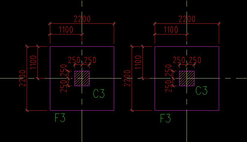
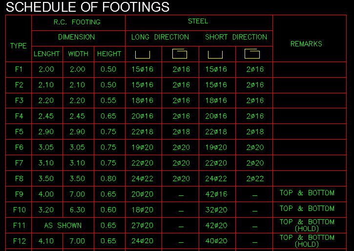
Schedule of footings:
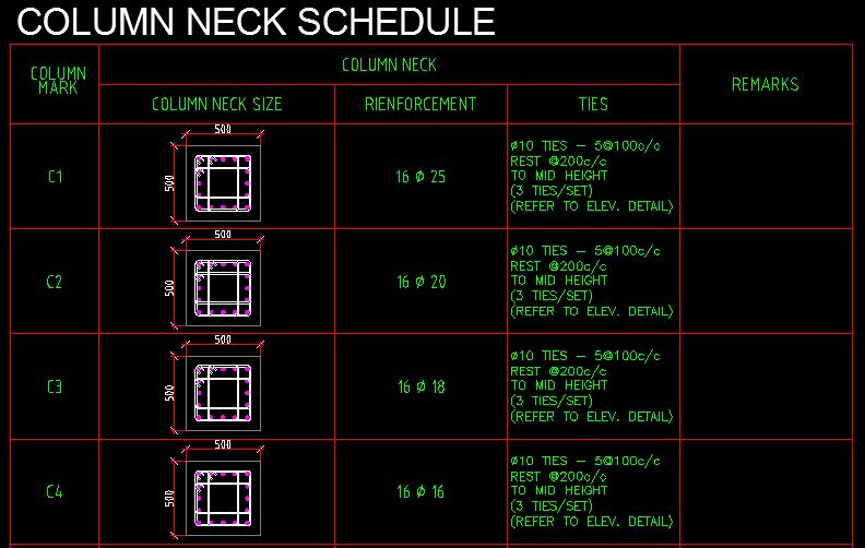
Column Neck Schedule:
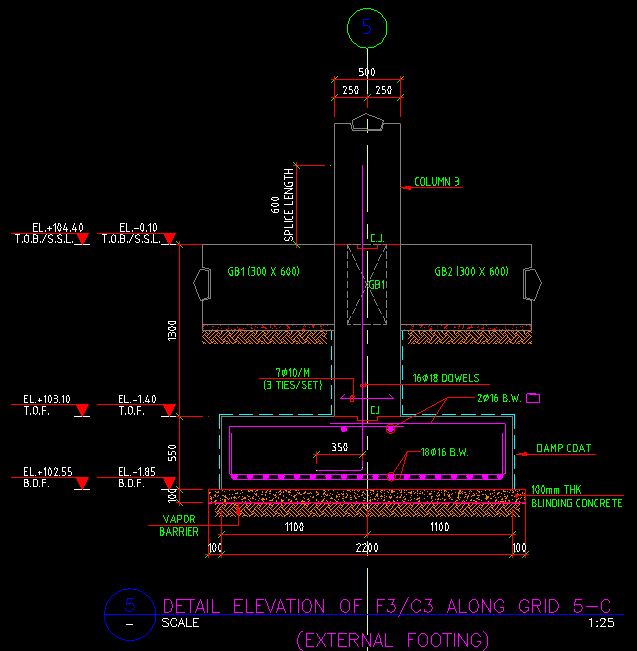
Detailed foundation reinforcement section:
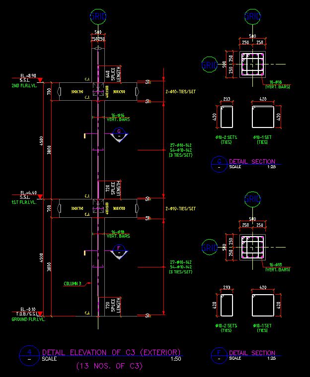
Detailed column reinforcement section:
Wall plan from footing to the ground floor:
Wall plan from the ground floor to first floor:
Wall detail section:
Detailed wall reinforcement elevation:
Have you done shop drawings before? If you are looking for someone to do shop drawings, please let me know. Anyway, moving forward, we now have Revit which makes it easy for us to develop plans, sections, elevations, and details. Any updates you do, say for instance moving the door opening from one location to another on the plan, will also update your wall elevations and this saves time for you to actually re-draw on your wall elevation the new location of the door opening.
The thing is, I got involved in a project where I am asked to provide reinforcement intent. I want to share with you my way of doing it and if you think there should be a much better way of presenting reinforcement intent, please don’t hesitate to share your view. I want to learn from you and I hope you don’t mind sharing your own view on how to standardize the reinforcement intent presentation on sheets and how do you normally prepare it? Perhaps you could send me a sample of your work and what you share to me will be highly appreciated.
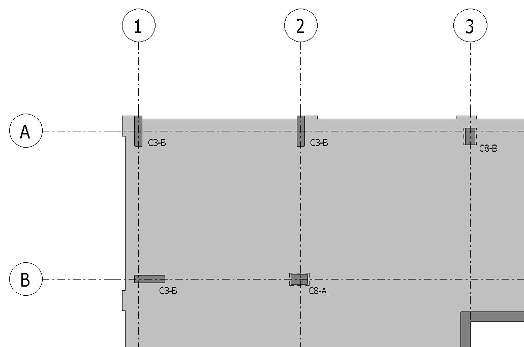
I’ve seen some drawings that provided tags on the plan similar to the one below.
And another sheet where all the sections showing the reinforcement distribution are drawn similar to the one showed below.
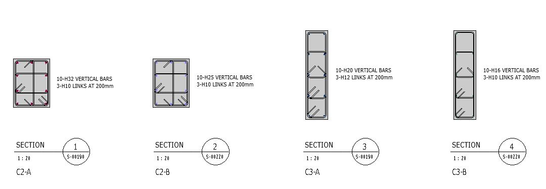
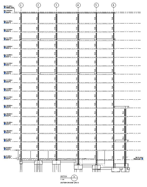
All my columns in the project I’m currently working on can be covered by creating sections. In this way I’ll see quickly at which level the vertical reinforcements will change and with that in mind, I no longer need to produce plans similar to the one above.
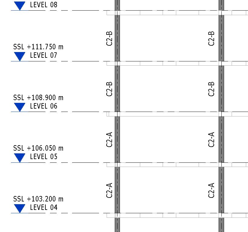
Here is one of the sections showing some member reference tags.
Let me have a closer look.
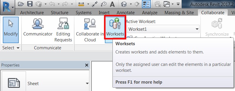
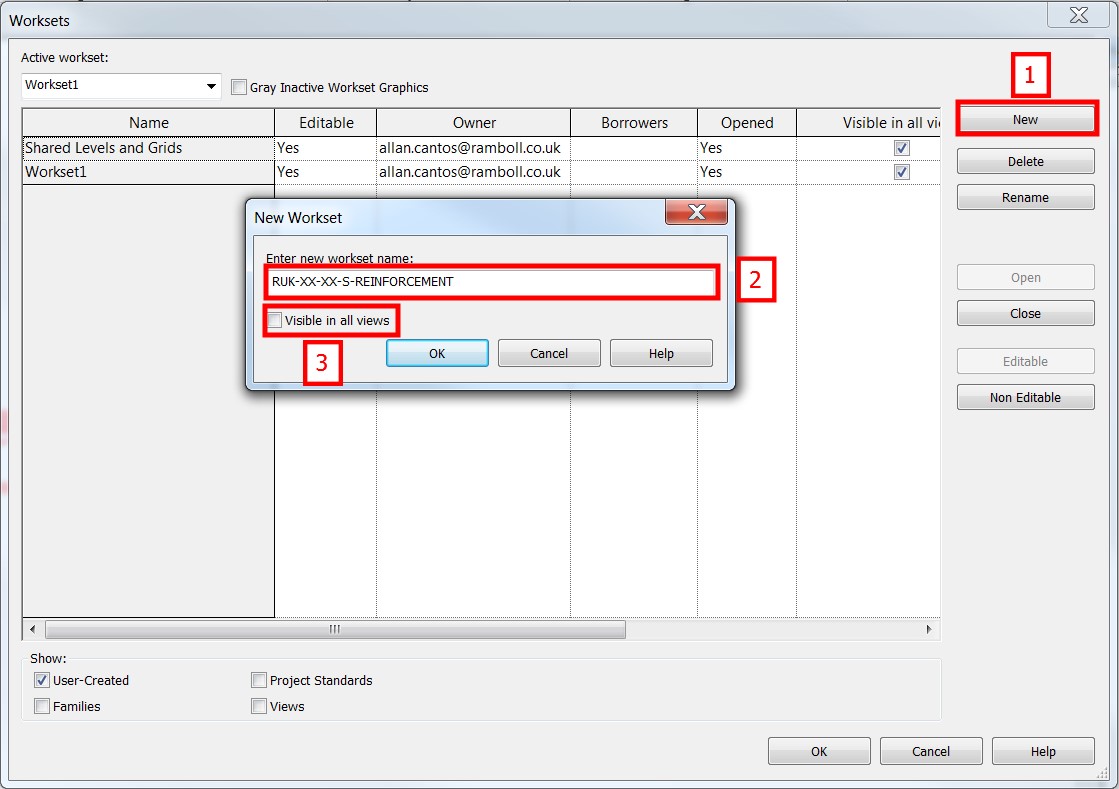
Now, here is my procedure. I’ll begin by creating a “Workset” for my reinforcement and I want to make sure that the “Visible in all views” tick box is unticked. In this way, I can only turn this Workset “ON” to views where I want my reinforcement to be shown. The Workset naming convention should follow your company standard.
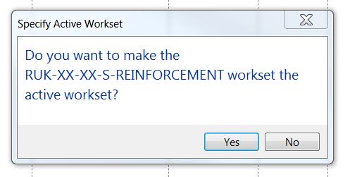
Then make that workset an active workset by selecting the “Yes” button.
Here is what you’ll see as default settings on your view template.

Next, I’ll create a view template or duplicate one that I already have and configure it to have the Workset for the reinforcement visible.

Then I’ll start in duplicating my floor level and assign the newly created view template.
Next is to create scope boxes and name the scope boxes accordingly.
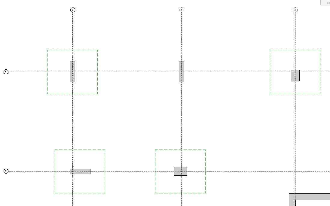
Here is where you will apply the scope boxes created.
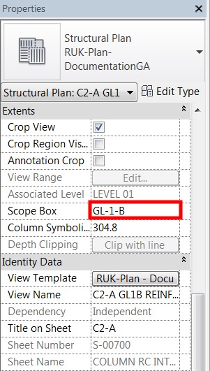
With this scope box selected, I am looking at my column at Gridline 1-B and I will have the view below. I configure my “View Range” to have it in the middle of the column so I won’t see beams and slabs for this exercise.
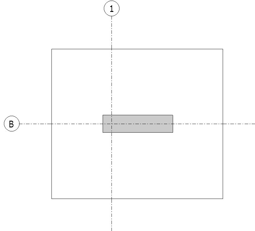
Next, I’ll hide the crop region and the gridlines and start tracing my reinforcement.
The question now is how they are actually drawn? Some of you may not be taking advantage of Extensions tools that we have on Revit. There is a quick way to draw these reinforcements only if you know the right tools to use. I’ve seen some technicians creating the reinforcement using detail lines. For this exercise, we will be using the Revit Column Reinforcement Extensions plug-in since I am looking at the column which is a 3D element.
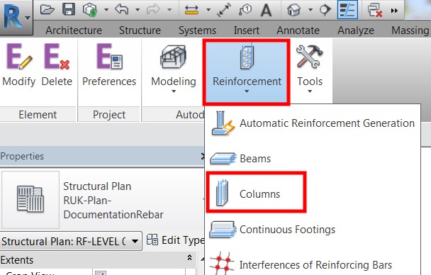
To start with, make sure the column is selected then look for the “Extensions” on the “Menu” options then under “Autodesk Revit Extensions”, choose “Reinforcement – Columns”.
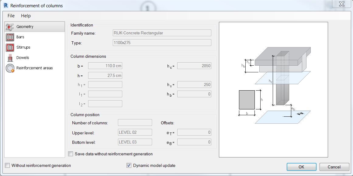
Revit will automatically detect the geometry properties of the column so you don’t have to worry about this. However, keep mind of some settings to make sure they are right.
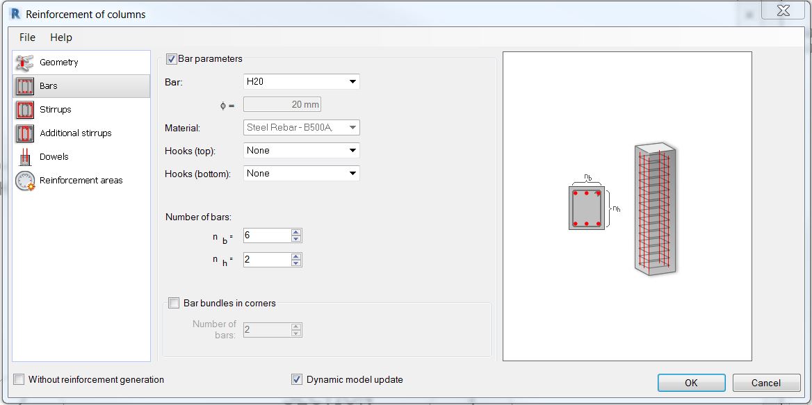
Next step is to specify the vertical bars. Other settings are self-explanatory anyway.
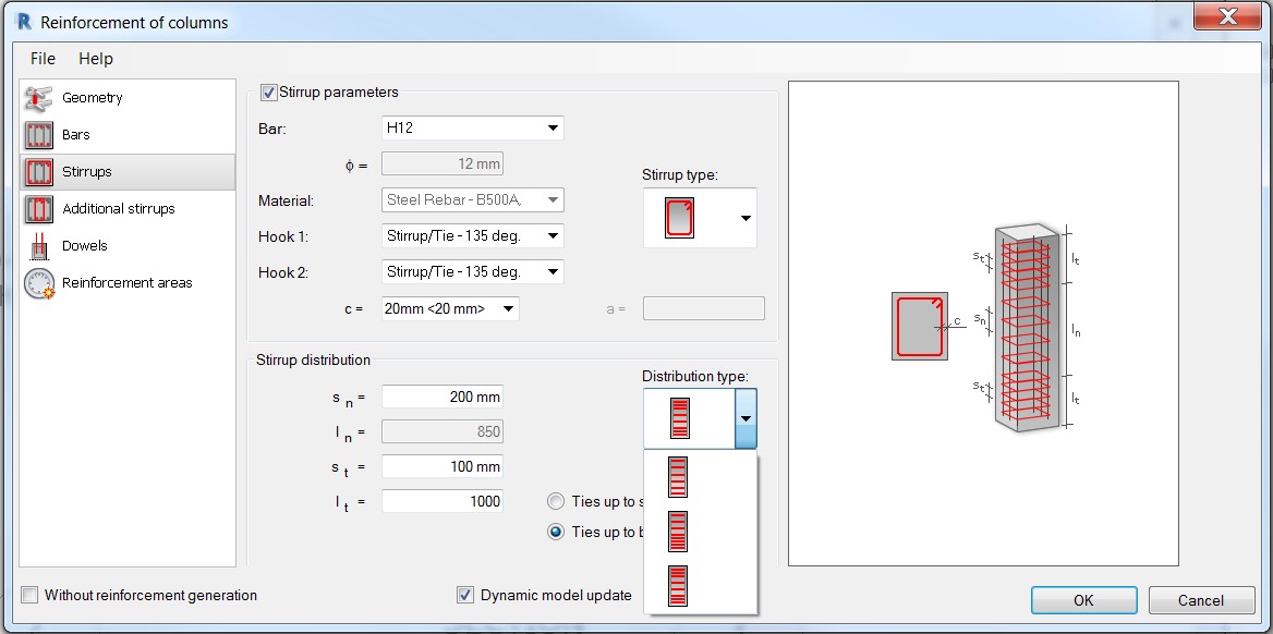
Next, move to “Stirrups” or other calls it “ties” and specify the desired stirrups bar diameter. Select the desired stirrup type and distribution type from the drop-down selection menu. The rest of the settings are based on the design.
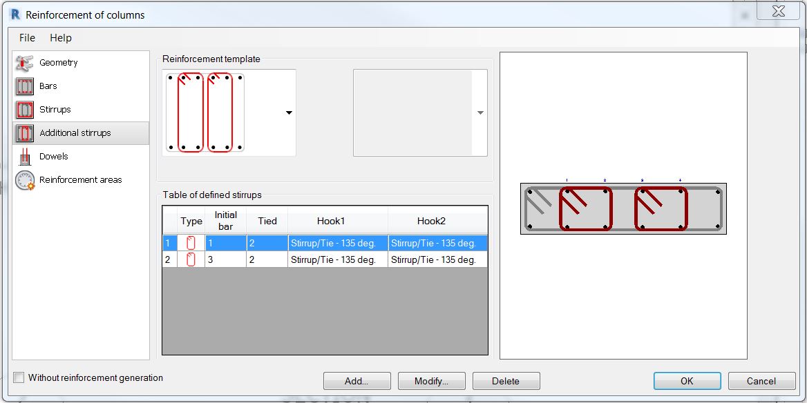
And finally, jump to “Additional stirrups” where you can choose from a given “Reinforcement template” the additional stirrups arrangement that matches your design.
I don’t have to worry about the next two options, “Dowels” and “Reinforcement areas”
Next, add a bit of information, place it on the sheet and I’ll have something like the one below.
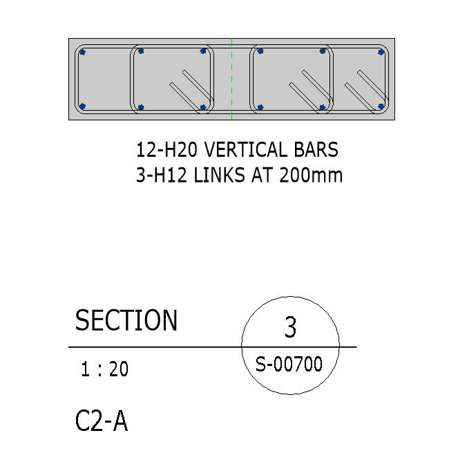
By the way, there will be some instances where you want to change the hook orientation and it can be done on the “Properties” tab.
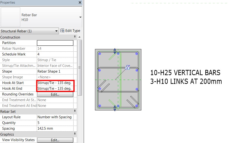
That should be it for the column. How about the walls? I’ll do a similar thing using Revit Extension.
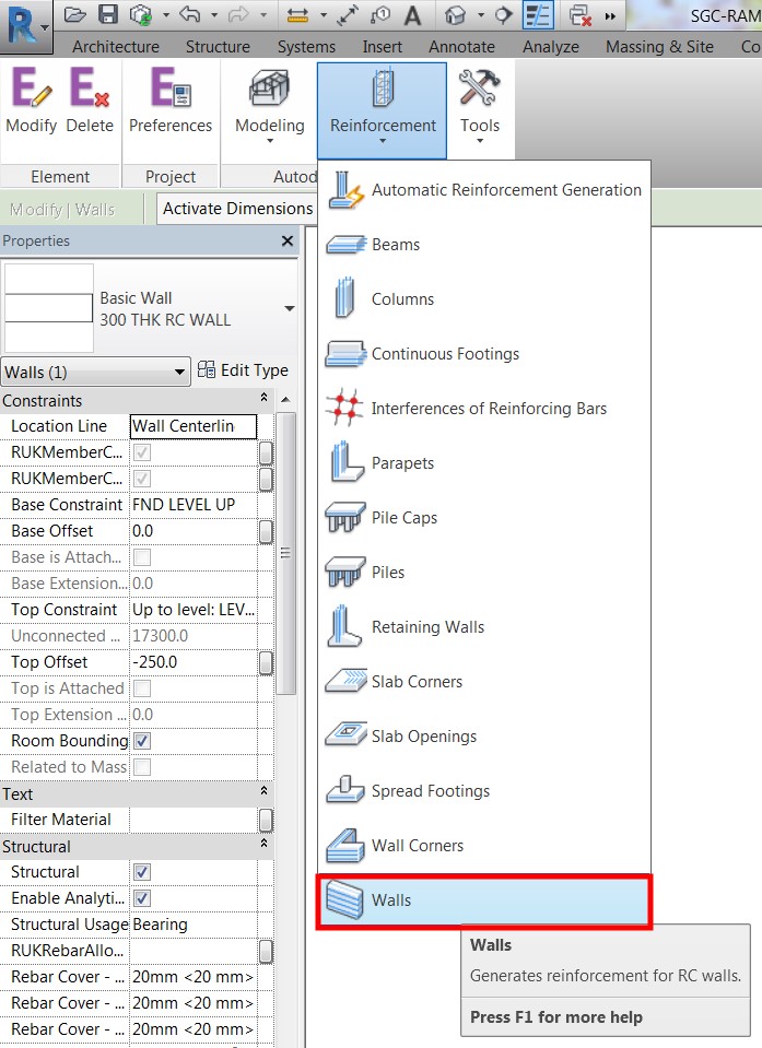
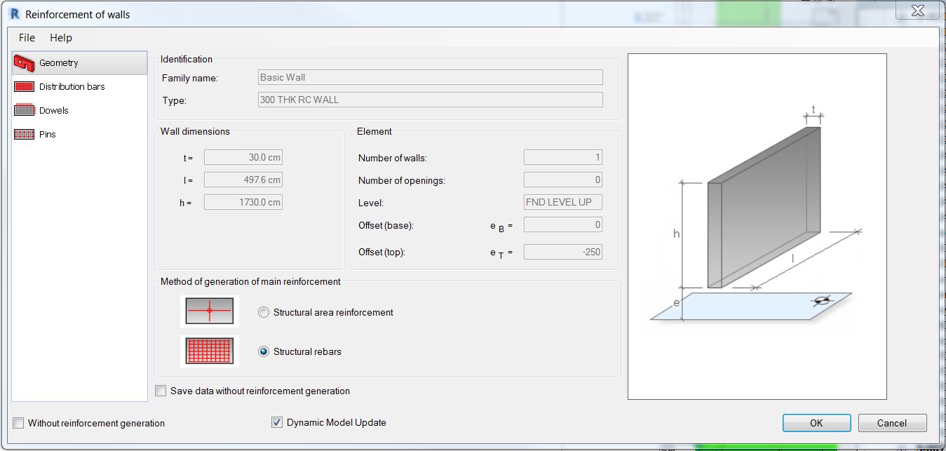
Similar to the column, you don’t have to worry about the geometry; Revit will automatically detect it for you.
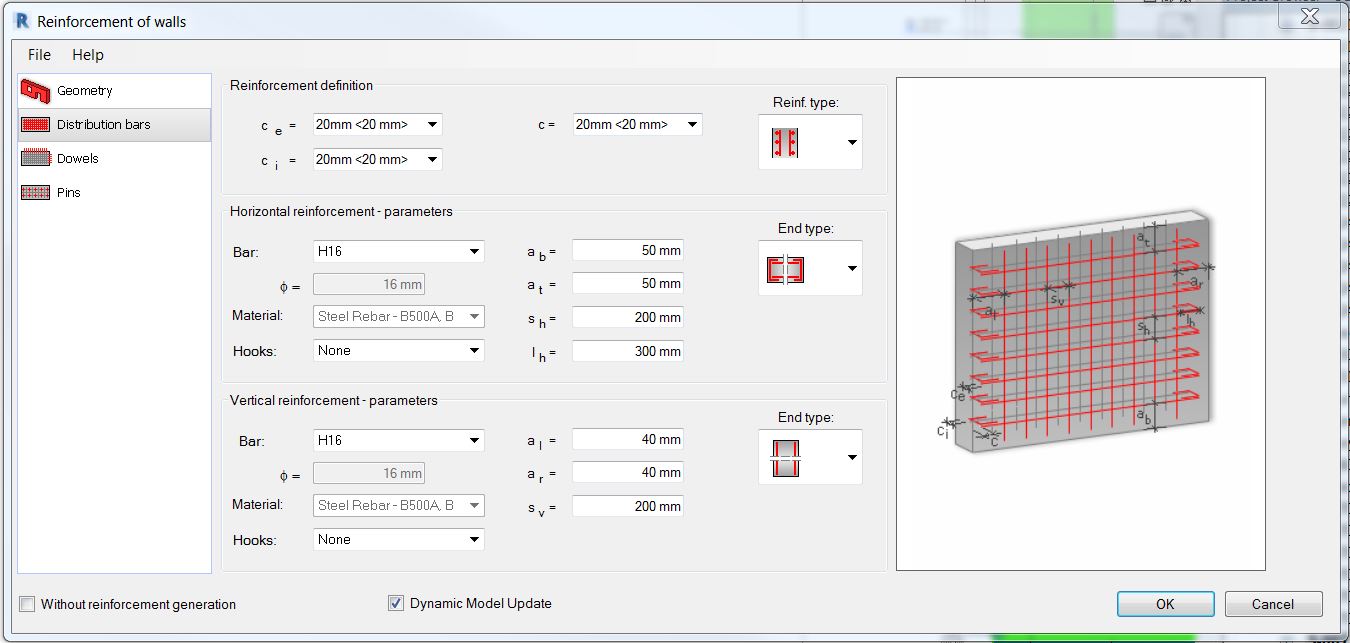
Next is to set up the distribution bars.
And then I don’t need to worry about setting up the next two option; Dowels and Pins.
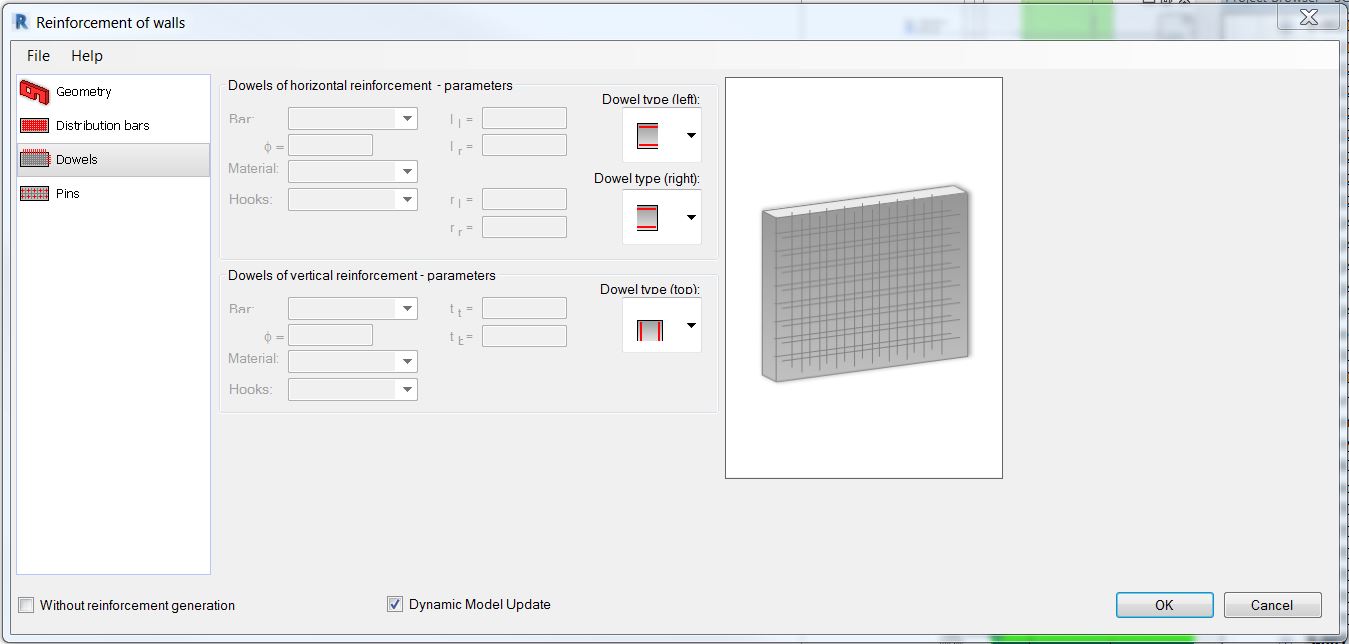
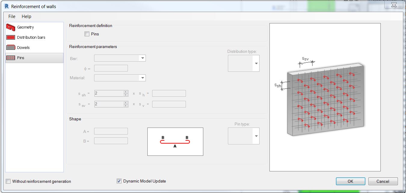
Here it is on plan with added annotations.
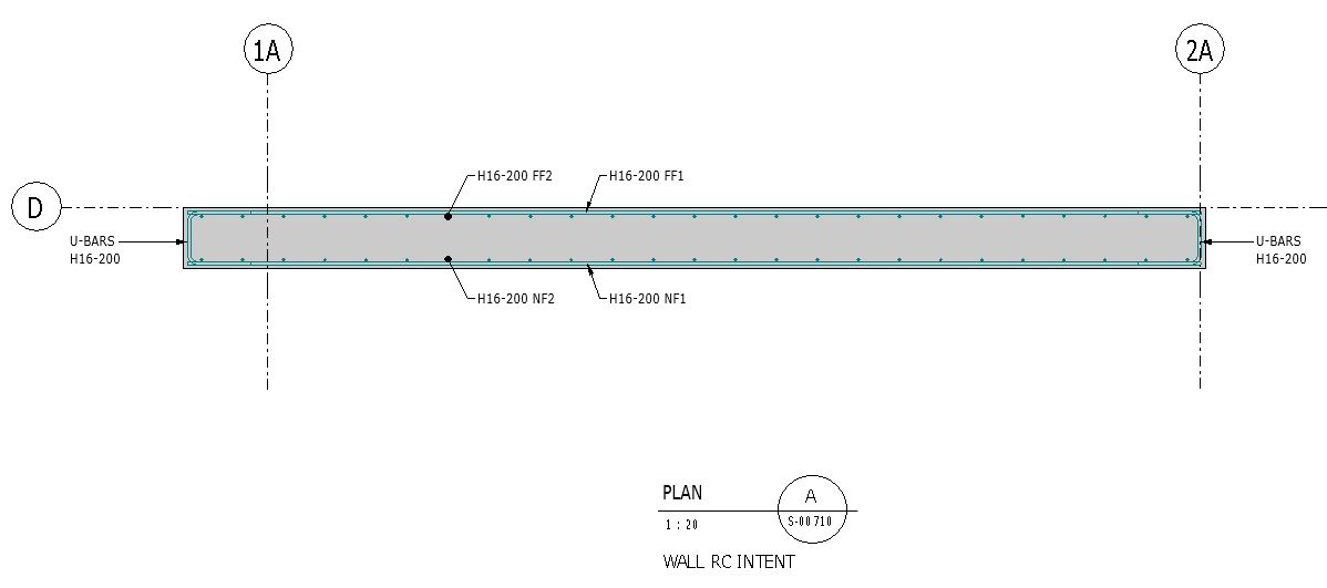
And here is the part where I’ll be needing your another input. Basically, I just drew some detail lines to show my vertical and horizontal reinforcements with additional information at the side showing the reinforcement sizes.
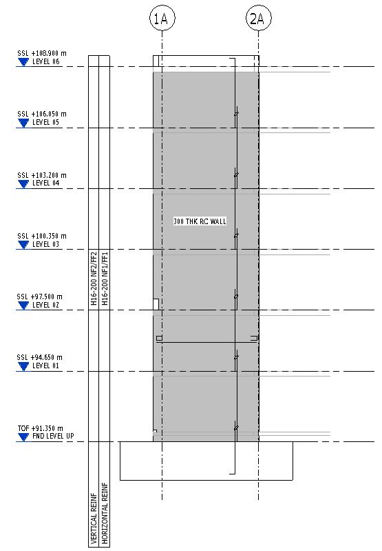
And that should be it. As before if you know of a better way, I am happy to learn from you so please don’t hesitate to share your view. I hope you don’t mind sharing your own workarounds on how to standardize the reinforcement intent presentation on sheets and how do you normally prepare it. I would appreciate it much if you could send me a sample of your work. Thank you in advance.
Until next time!
Best regards,
Allan Cantos


