Numbering Piles using Dynamo – Part 2 (No programming knowledge required)

Hi everyone. Today I’ll continue finishing the second part of assigning unique tags to all piles on my Revit structural model and for those of you who missed the first part, here is the link:

https://allscan12.com/index.php/2017/09/29/numbering-piles-using-dynamo-part-1-no-programming-knowledge-required/

We ended up with this node arrangement where I extracted the XYZ coordinates of each pile then filter the X and Y coordinates separately and finally create a sorted list of piles in ascending order with respect to X or Y coordinates.

Next, I set up my spreadsheet listing down in columns what I might need to export using Dynamo from my Revit model.

With that in mind, I started adding those nodes as additional information to be taken out of my sorted pile elements.

Then I’ll list them down in a list.

Convert the columns into rows.

Then time for me to build my export to excel node and connect the transposed list.

Hi “Run” and I will have something like this:

Now I can sort column “Y-COORDINATE” and “X-COORDINATE” in ascending order.

And the result is:

As you can see, I don’t have a problem with arranging the Y-COORDINATE in ascending order but, for whatever reason, Excel did not sort the X-COORDINATE in ascending order. Still looks random to me the highlighted cells and therefore I need to fix the arrangement first before applying “PILE REFERENCE” information.

Here is how it will look like after fixing the sorting arrangement with “PILE REFERENCE”.

And I am done with the first part of exporting the information. Next step is to import back those “PILE REFERENCE” information using read from excel file node in Dynamo.

Before jumping back to Dynamo, I need to do one more step on my excel file by sorting the “PILE ID NUMBER” in ascending order.

Then jump to Dynamo and I’ll start by setting up the nodes to read the excel file then hit “Run”.

Next, I’ll remove the list that contains my column titles.

Convert the columns into rows.

Then I’ll isolate the “PILE REFERENCE” and “PILE ID NUMBER”.

Then add the node to specify the element parameter to use where the “PILE REFERENCE” information will be written.

After that, I need to specify which elements to connect to the “element” input of my “Element.SetParameterByName” node.

Basically, I need to repeat those nodes in isolating the “PILE” from my structural category. Here are the nodes needed.

By examining the list result, the list is now arranged in ascending order which matches with our excel file.

Now I am ready to connect the “in” output of my “List.FilterByBoolMask” node to my “element” input of my “Element.SetParameterByName” node.

My script is now done and I am ready to hit “Run”.

The result:

Now it’s your turn to give it a try and if you have any other information to add to improve the process, please share. I am happy to learn from you. My door is open to find out your Python script or any other processes to remove the process of editing manually, by sorting, the spreadsheet as this will likely cause a human error.

Once again, this process does not include any Python node which requires programming knowledge. Not everyone is knowledgeable in programming language and this is the reason for me to demonstrate that it can be done using the basic Dynamo nodes.

Yesterday I organized a knowledge sharing session where our Revit Leader introduces us to the additional features of Revit Apps called “IdeateApps for Revit” and one of its features is being able to renumber most elements by selection, path, or auto-update method. Once I get the chance to test this for piles, I’ll share to you my experience and how it works.

I hope you like it and until next time.

Have a great weekend!

Cheers!

Allan Cantos

Numbering Piles using Dynamo – Part 1 (No programming knowledge required)

Hi! How are you doing? I trust you are well. It’s been a few weeks since I posted something relevant to Revit. That’s because I have been busy these past weeks.

Now I find some time to document the process of looking at assigning unique tags for all my piles using Dynamo. This is for a new project consists of piled foundations and since I’ll be using Revit 2017, some apps or plugins are no longer available for use for this version. Dynamo help is my only option as eventually, I’ll be numbering my piles anyway. So I’ll make a test first before actually applying this to the project. This is not only for my own reference in the future but to share with you the process as well and hope you’ll find this useful. If you like it, don’t forget to give it a ‘Like’. If you have some knowledge to share, don’t be shy and keep it yourselves, help others learn from your hidden knowledge and experiences. Let’s begin!

First I open my Revit and I started placing piles and pile caps in random and in different pile cap types as shown. They also come in different pile diameters.

Next, I’ll create a Structural Foundation Schedule.

I used Type, Mark and Type Mark

Then we have a built-in text parameter within our company Revit Structural Template called ‘RUKViewFilter’ which I’ll use to specify whether the element is a Pile or Pile Cap. Any text parameter will do actually.

Add a little bit of formatting to schedule Piles only.

Then I rename the schedule to ‘PILE SCHEDULE’ and add the other necessary parameters I normally use to create Pile Schedule. Mine looks like the one below without the columns for the loadings.

While the ‘PILE SCHEDULE’ is still open, I highlight all the piles then I go to my view where I can only see my piles (in my case ‘PILE LEVEL’), select all the piles and assign a tag by ‘Mark’.

And I should have something like this:

The goal of this demonstration is to provide a unique ‘PILE REFERENCE’ for each pile and to complicate things, I want the Pile Reference to be added in ascending order which starts from the one nearest to (0,0) coordinates. The naming should start by looking at the Y-coordinates first that is nearest to origin then followed by X-coordinates. I manually assigned the tags for each pile (see below) and I’ll see if I’ll be able to get the same tagging arrangement using Dynamo.

Let me hit ‘Undo’ button to remove all the tags because I want Dynamo to do it for me.

After that, let me jump to Dynamo and begin the exciting part: building the graph or script.

Now open Dynamo.

If you have two or more versions of Dynamo installed on your machine, use the latest one.

Create ‘New’ file

Don’t forget to save the file first.

Next, I begin with pulling out all the structural foundation categories.

As you can see, I have piles and pile caps. I am after only with piles and therefore I need a way to separate them. If you remember I have a filter called ‘RUKViewFilter’ which allows me to specify whether the element is a pile or a pile cap.

Next node I need is called ‘Element.GetParameterValueByName’ and under the ‘parameterName’ I’ll connect the string called ‘RUKViewFilter’.

Next is to split PILE to PILE CAP. I need a node called ‘==’. What is this node does is to compare x input to y input and gives you a true or false result.

Then I need a node called ‘List.FilterByBooMask’ which separate true and false results based on the input list.

Now I need the location in XYZ coordinates of all my RC piles. To do that I need a node called ‘FamilyInstance.Location’.

Then I’ll isolate the Y-coordinates.

And next is to use ‘List.SortByKey’ node to sort the Y-coordinates in ascending order.

However, I need a list to connect to the ‘list’ input of my ‘List.SortByKey’ node. Therefore I need to create a list using ‘List.Create’ node and I want to list down the pile type and the coordinates.

Transpose the list using ‘List.Transpose’ node so I’ll have the pile type and it’s corresponding coordinate location.

Then connect the transposed list to the ‘List.SortByKey’ node as shown.

Now I have a list of piles in ascending order with respect to the Y-coordinates.

Let me do sort my piles in ascending order with respect to the X-coordinates and I should have something like the one below.

Now here is where the part-1 will stop. Next step is to figure out how to sort my list of piles in Y-direction first and followed by X-direction simultaneously instead of having two separate lists in ascending order with respect to Y-coordinate and X-coordinate respectively.

I came across in one of the posts on LinkedIn from Mr.Alexander Tohidi about the use of an algorithm called ‘Bubble Sort’. Here is the link to his interesting post on LinkedIn: https://www.linkedin.com/feed/update/urn:li:activity:6317768340404342785

Just to give you a bit of idea, ‘Bubble sort’ is a simple sorting algorithm. This sorting algorithm is a comparison-based algorithm in which each pair of adjacent elements is compared and the elements are swapped if they are not in order.

Another way to do this is to export my list to the spreadsheet and sort it there then assign my instance pile reference parameter and push it back to Revit using ‘Excel.ReadFromPile’ node in Dynamo (this requires another Dynamo file).

I’ll post the part-2 as soon as I have completed the test.

If you know a better way or if you have any questions just let me know and I’ll do my best to answer!

Creating Structural Connection Family for Cross-laminated Timber (CLT) – Part 1

Hello there. I trust you are all doing well. CLT or Cross-laminated Timber demand continues to grow rapidly as the possibilities for using this versatile and sustainable material are vast.

If you want to find out more about CLT, here is the link to start with:

http://www.ramboll.co.uk/about-us/key-themes/cross-laminated-timber

Here are the other links that I visited for more information:

http://www.greenspec.co.uk/building-design/crosslam-timber-introduction/

http://www.bre.co.uk/filelibrary/pdf/projects/low_impact_materials/IP17_11.pdf

Now that you know about CLT, let me begin by looking at creating one of the CLT structural connections as a Revit family.

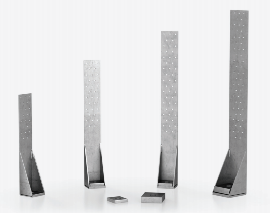
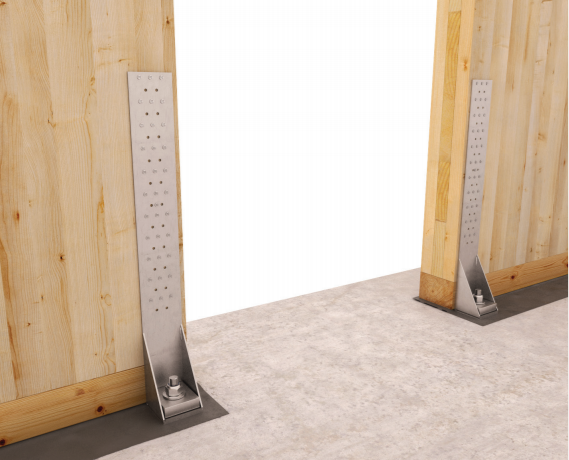
I’m providing support to our new technician in the office in my team and one of the tasks we asked him to do is to create a Revit Family for the CLT brackets/connections. I’ll be looking at creating the one shown below.

Here is the link for the company who is producing this angle bracket support:

http://www.rothoblaas.com/products/fastening/brackets-and-plates/tensile-angle-brackets-and-plates-for-buildings/wht

And here they are in Revit:

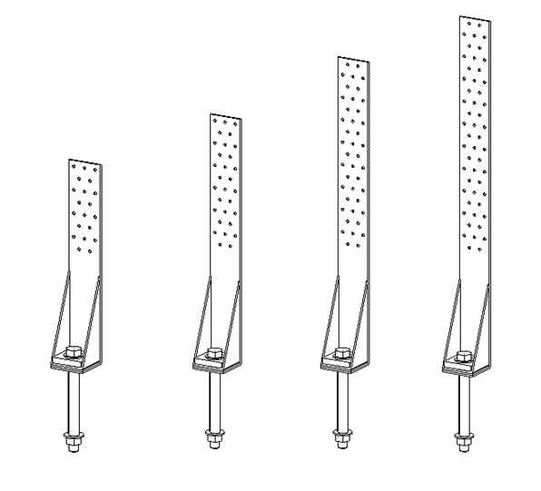
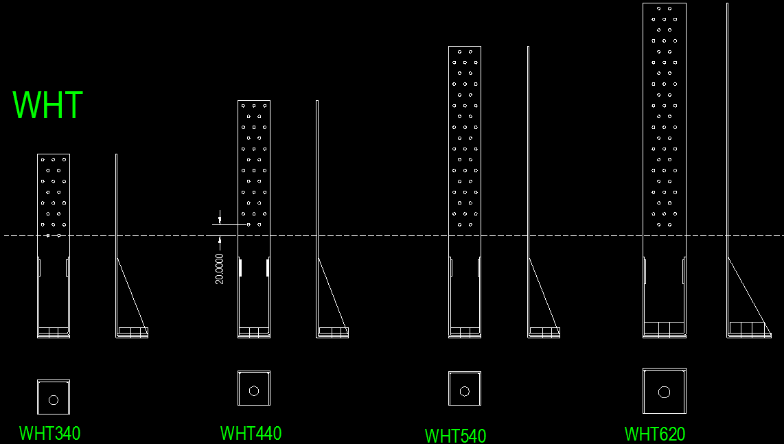
I only have one Revit family with four types shown below.

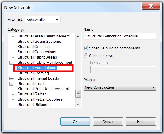
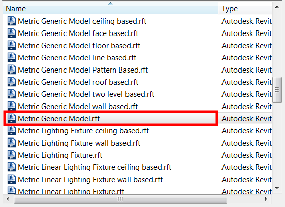
First, I create a new family and use “Metric Generic Model.rft” template file.

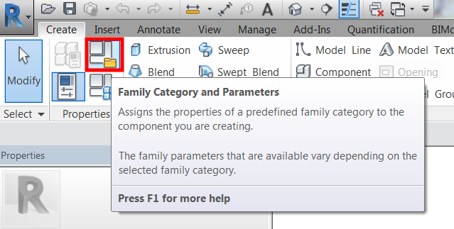
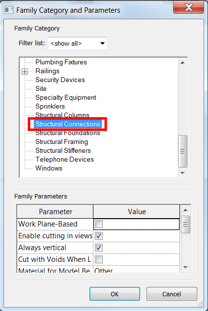
Click on “Family Category and Parameters”

And I’ll use “Structural Connections”.

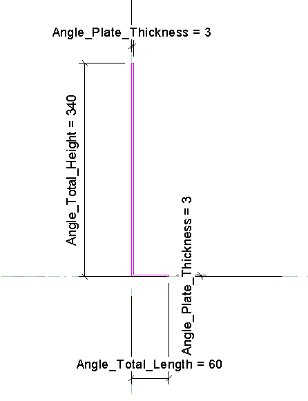
Jump to left side view, or right side view, whichever you prefer, and start tracing the profile of the angle using “Extrusion”.

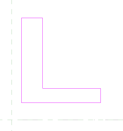
Lock the bottom side and the left side to the horizontal and vertical reference planes respectively then add dimension.

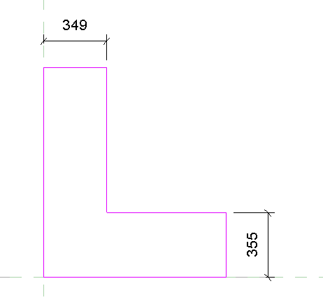
Highlight the dimensions and assign a parameter.

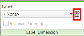
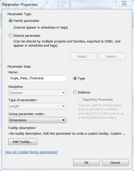
For this exercise I’ll be using “Family parameter” and I’ll name these dimensions as “Angle_Plate_Thickness” and under “Dimensions” Group parameter then click “OK”.

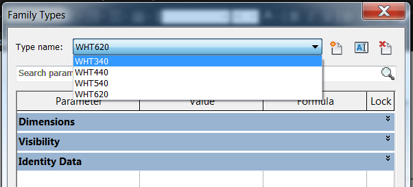
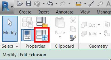
Click on “Family Types” icon.

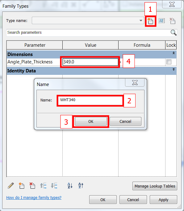
And create a “New Type”, call it “WHT340”, click “OK” and change the thickness to, say 3.

Select the profile, click “Edit Extrusion” then add dimensions to height and length and assign a parameter.

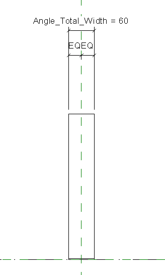
Then go to “Front view”, add dimension to specify the total width then assign a parameter. I’ll call it “Angle_Total_Width”. Make sure the left and the right side are in equal dimension from the vertical reference plane as shown below.

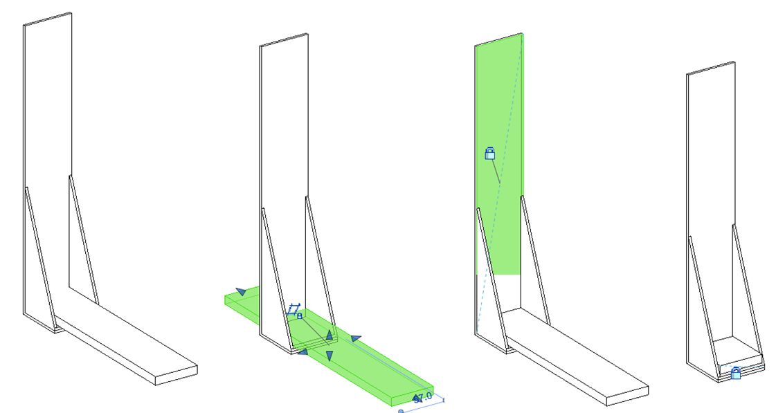
Next, I’ll create the angle shown below.

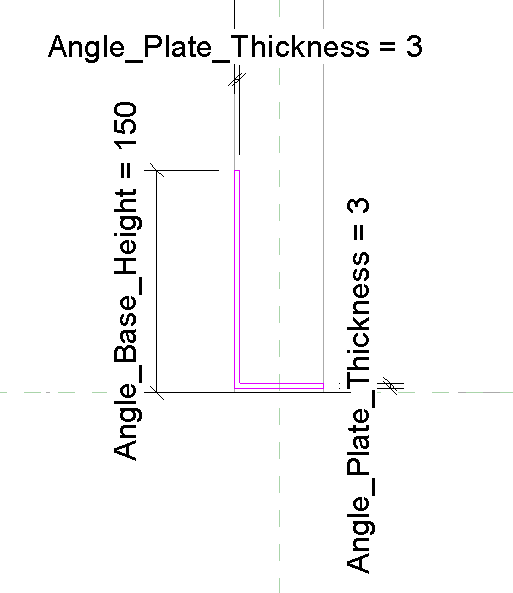
While in “Front” view, trace the profile of the angle.

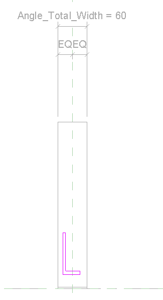
Lock the left side and the bottom side of the angle on their right places, add dimensions and assign parameter. The plate thickness is also 3mm and the angle height is 150mm.

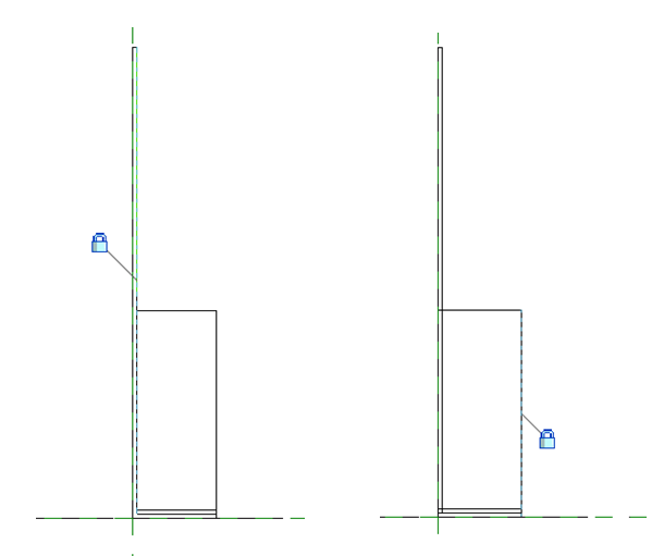
Go to the left or right side view and alight the end of the angle to the total length of the main angle and lock it as shown. One thing to make sure as well is not to extend this base angle to the main angle.

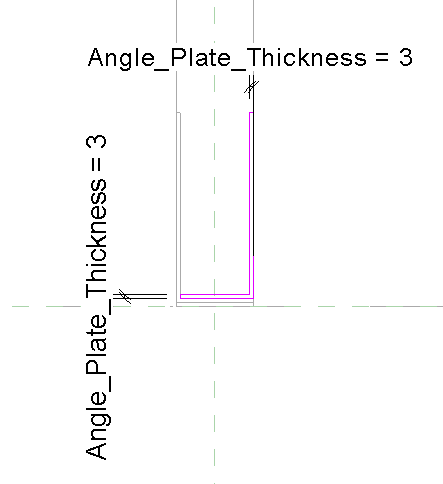
Next is to create the angle for the right side by following the same procedure above.

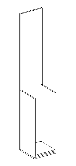
And I have now this 3D view so far.

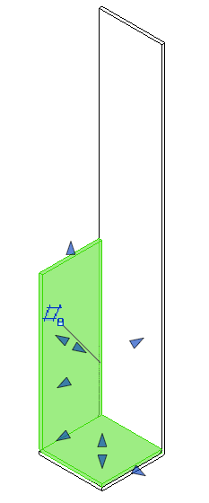
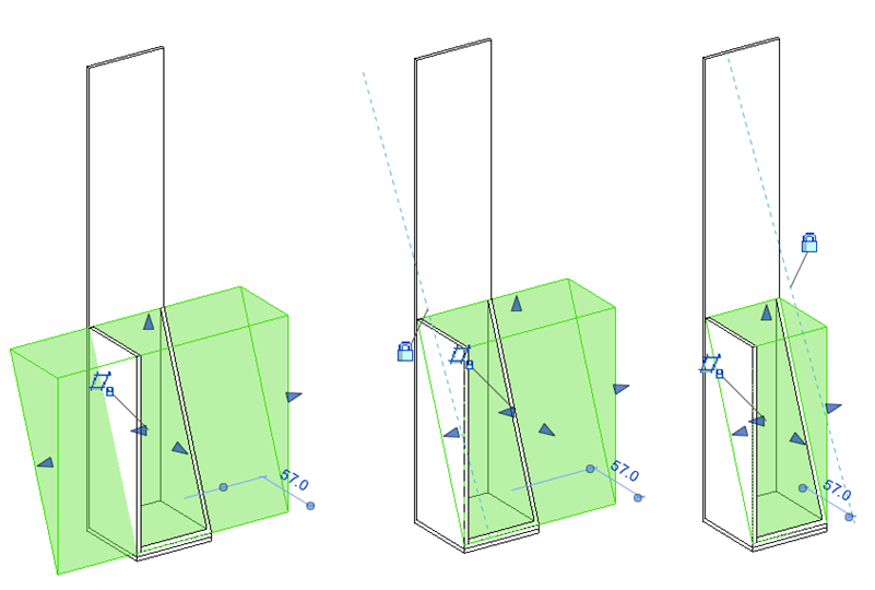
Next is to create a void extrusion to make to base angle triangular shape.

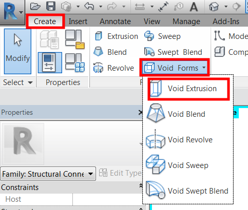
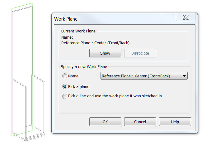
Set the “Work Plane” to the face of the base angle by using “Pick a plane”.

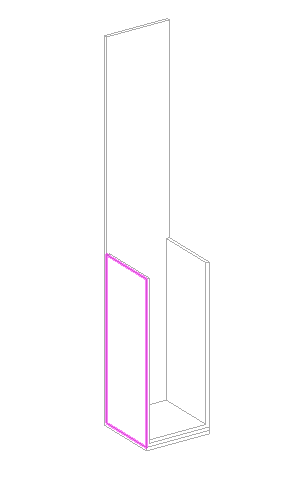
Then select the highlighted plane.

Then start tracing the triangular void as shown. Once you’re happy and lock them in the right position, click “Finish Edit Mode” icon represented by “Green Check” icon.

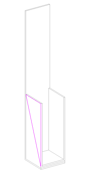
One thing I do to make sure they adjust accordingly with my assigned dimensions is to lock both ends to each face of my base angle.

Next, is to create the, I’ll call it, baseplate as shown.

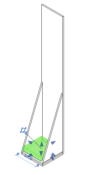
Go to “Front” view and create an extrusion. Add dimension for the thickness of the base plate and assign a parameter. Lock the left, right and bottom face as shown below.

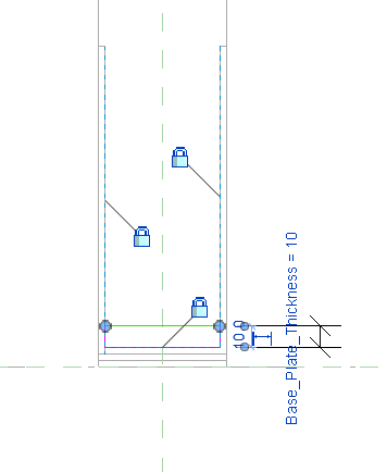
Go to “3D” view and lock the length of the base plate accordingly as shown below.

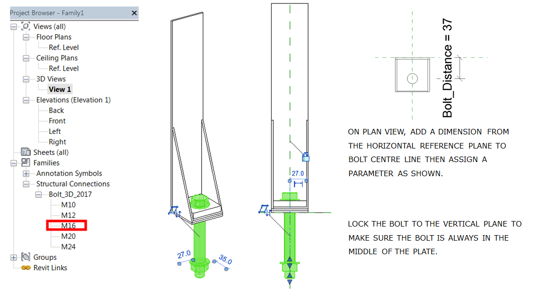
At this stage, I’ll be adding a bolt. Here is the link for those who would like to have a copy of the “Bolt Family” I used in this exercise.

https://www.dropbox.com/s/c1eozd0aawx6ix2/Bolt_3D_2017.rfa?dl=0

Save the project and I name it “WHT CLT Connection Detail”. I should have done this at the beginning.

Here is the link for the “Circular Void” Generic Model void family that I’ll be using in the next step.

https://www.dropbox.com/s/t8ts66jfyp00zzx/Circular_Void_2017.rfa?dl=0

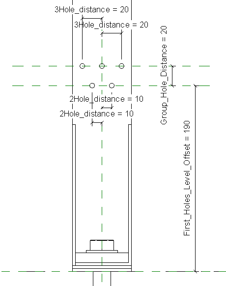
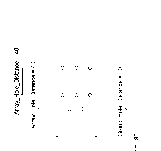
Load this into the project. Create a reference plane, add a dimension and assign a parameter and I call it “First_Holes_Level_Offset”. Add two circular voids to the face of the vertical plate, lock them to the newly created reference plane, add dimensions and assign a parameter. See below.

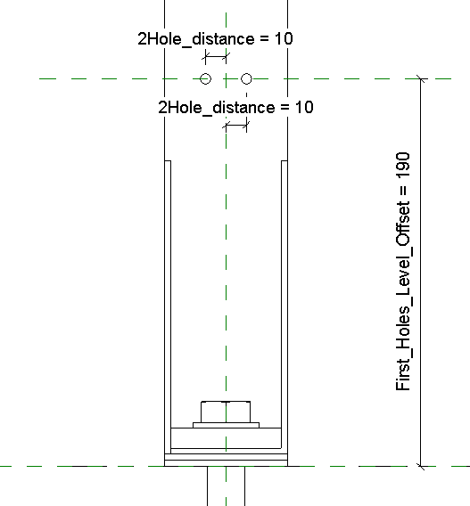
The reason of assigning a parameter for the first hole level offset is because the other 3 types holes start 20mm higher than the smaller type as shown.  This will give me control when I come to create the rest of the types.

Create a new reference plane above the 2No holes. Add dimension and assign a parameter.

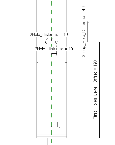
Next, add 3 holes on the same face of the plate and lock the middle one to the vertical reference plane. Lock the left and right holes to the middle hole horizontally. Add dimensions from hole to hole horizontally, assign a parameter and call it “3Hole_distance”. Then lock it to the newly created horizontal reference plane.

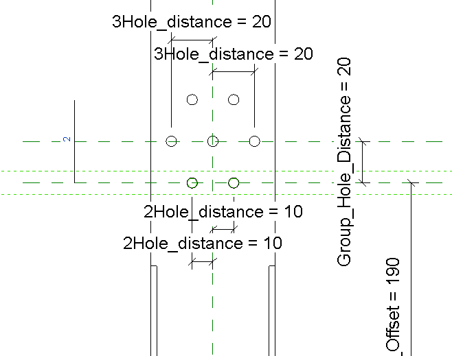
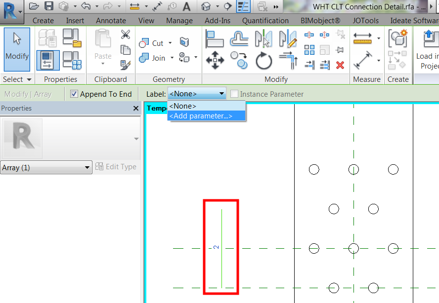
Next, select the 2No holes and create an array. Accept the default array settings for now then left click anywhere and drag to a certain distance and left click to finish the command. Make sure the “Group and Associate” box is ticked.

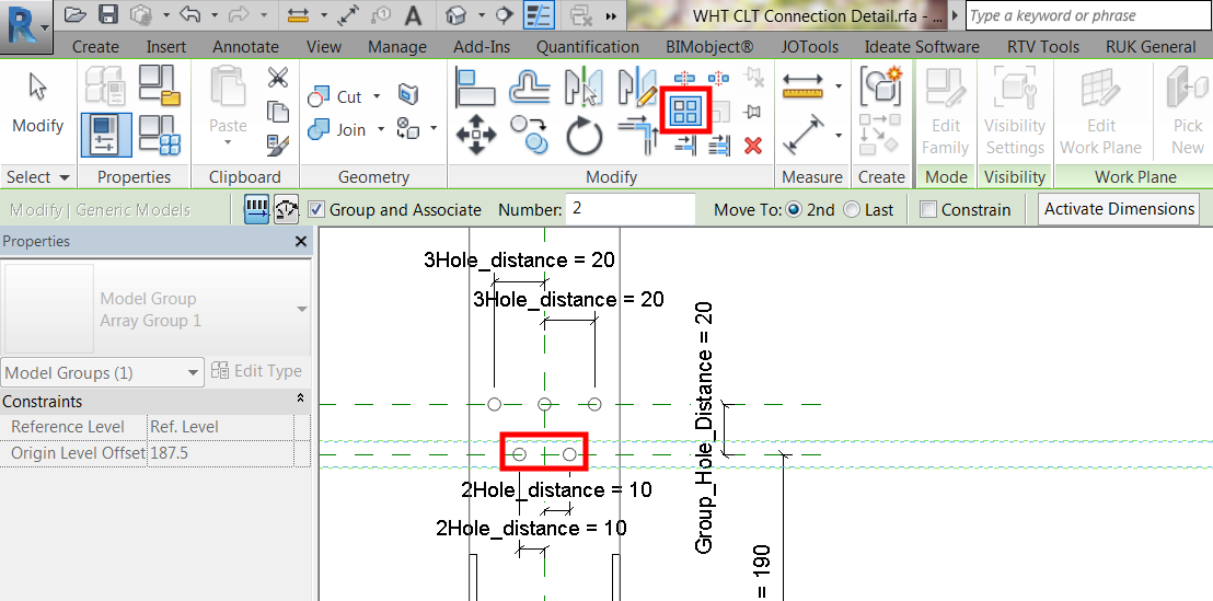
When you highlight the original 2No holes, you should be able to see the number of arrays; in this case, I should be able to see “2” counts.

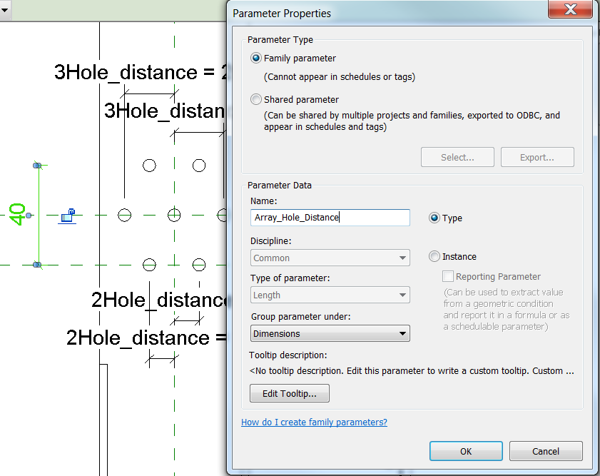
Add dimension between 2No holes in an array then assign a parameter

I’ll call it “Array_Hole_Distance” under “Dimensions” group parameter.

Do the same thing for the 3No holes. Create an array, 2 counts are enough, for now, then add dimension and assign the same “Array_Hole_Distance” parameter to the dimension.

Now it is time for me to parametise the array count. This will give me the flexibility to adjust the number of the array as the plate goes higher.

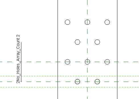
To do that, select the bottom 2No count holes (now in a group) and you’ll notice the number of the array. Select the array count and assign a parameter.

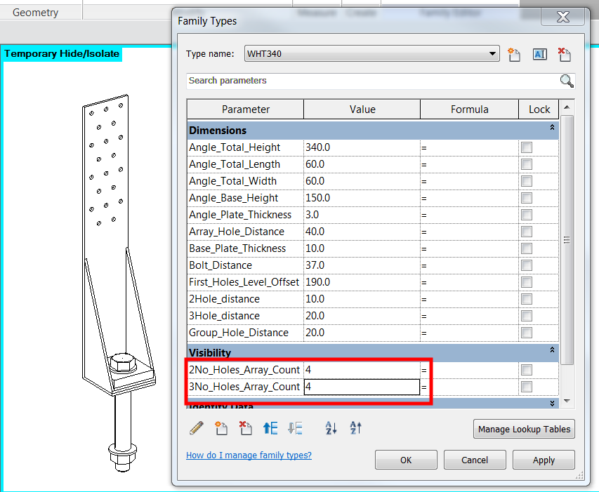
I’ll call it “2No_Holes_Array_Count” and group them under “Visibility”.

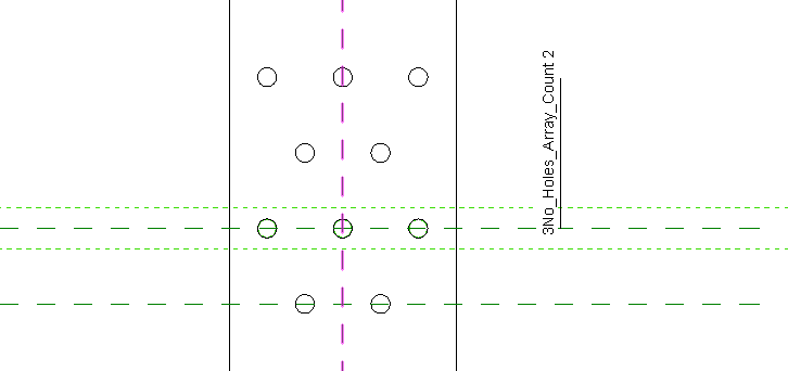
Do the same thing for the “3No count holes (now also in a group) but this time call the parameter “3No_Holes_Array_Count”.

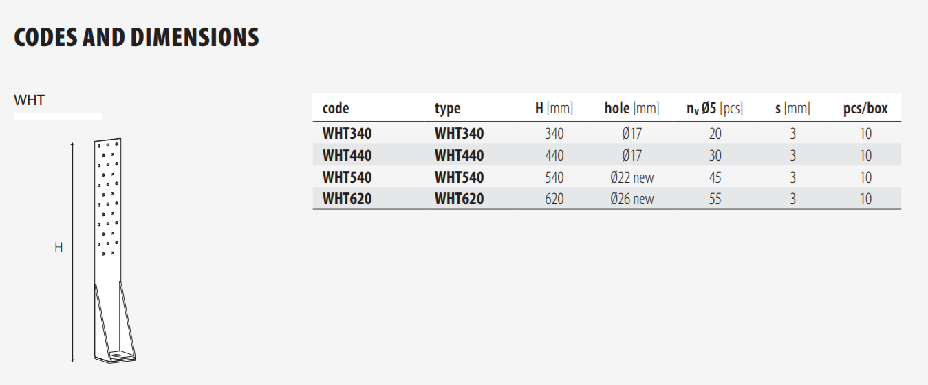
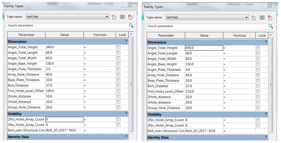
Looking back again to the image below, Type WHT340 have 4 count of 2No holes and 4 counts of 2No holes.

Simply update the values and I am done!

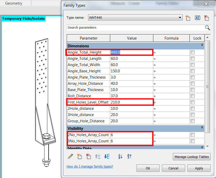
Now I am ready to create the other 3 types. Click on “New Type” and update the parameters highlighted as shown.

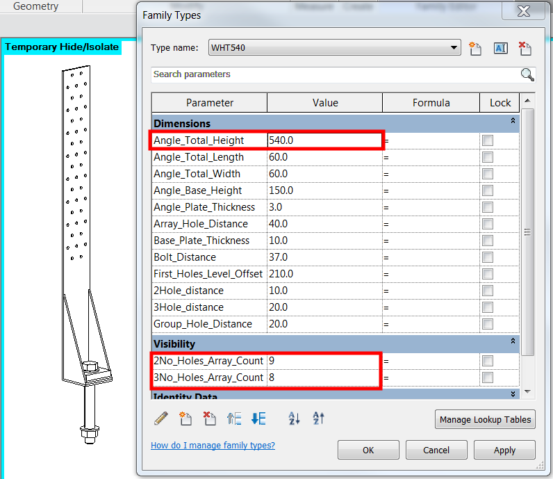
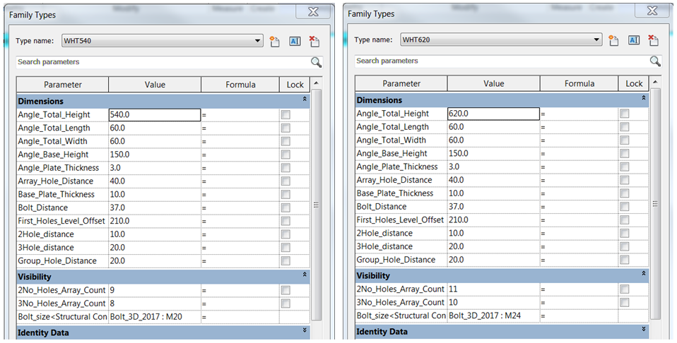
Next, create the 3rd type which is WHT540 and update the parameters highlighted as shown.

Finally, create the 4th type which is WHT620 and update the parameters highlighted as shown.

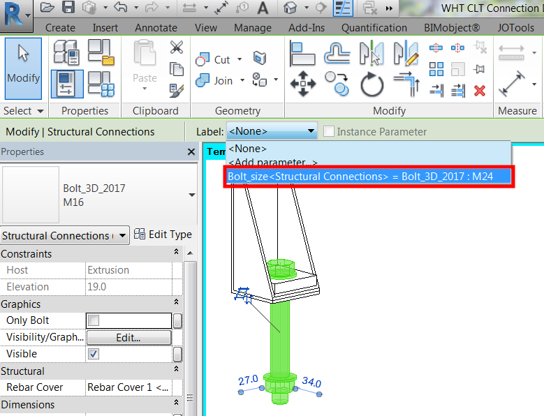
I believe I missed about the bolt size. Ok, let me parametise the bolt size. Going back to the image below, I can say that WHT340 and WHT540 use the M16 bolt, WHT540 use M20 bolt and finally WHT620 use M24 bolt.

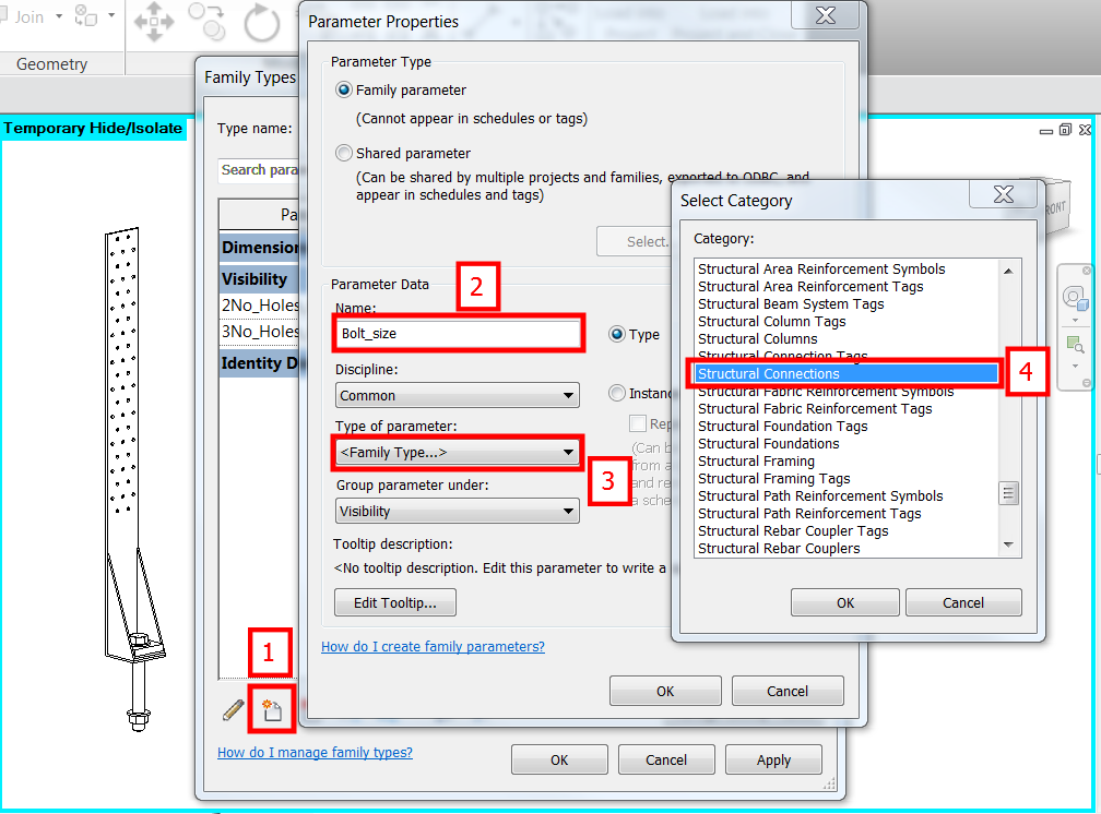
Let me create a new parameter and call it “Bolt_size” and I’ll put this parameter under “Visibility” group parameter.

Now select the bolt and assign the newly created “Bolt_size” parameter.

Here is the completed list of parameters I used for this family.

And that should be it. If I’ve left out any info that you want, or if you have any questions, just let me know and I’ll do my best to answer!

I am open for discussion should you want help in producing Revit family for your product.

Cheers.

Allan Cantos


Positive SSL