#Revit_Tips_001

Hello there.

If you are one of those Technicians who is producing drawings from a reference view Revit models, this Revit topic is for you.

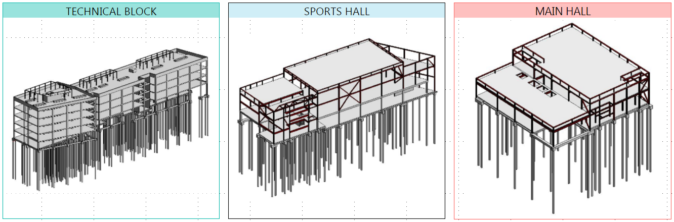
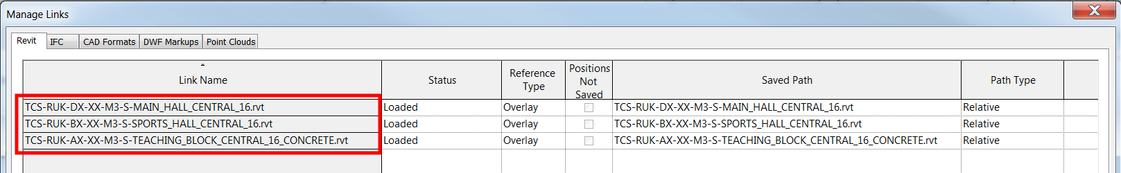
Now here is the situation, the project has 3 separate models; each one has its own Revit file.

Then there is a Revit file called “Sheet Model” where these 3 models are referenced in.

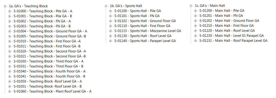
The views were generated by mimicking the levels of each building to the new “Sheet Model” Revit file and use these views to create the sheets shown below.

We managed to issue the drawings last March 2017 without any problem with the views and after that, because I got busy with another project, this project has been transferred to another Technician.

I got a call from this Technician asking for help wherein he was having a problem with a reference view of a general arrangement or plan view not appearing properly on his “Sheet Model” after doing some updates. He spent an hour trying to figure out how to fix the issue.

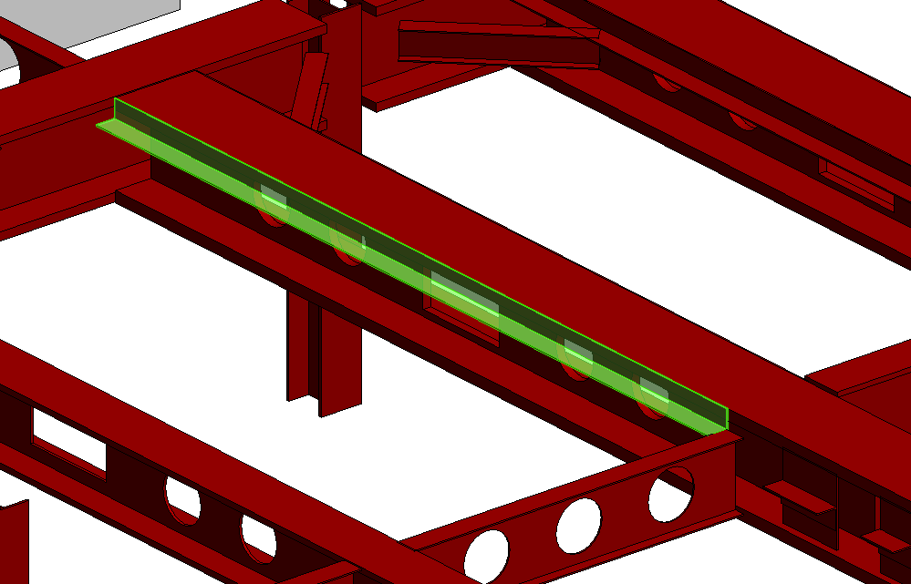
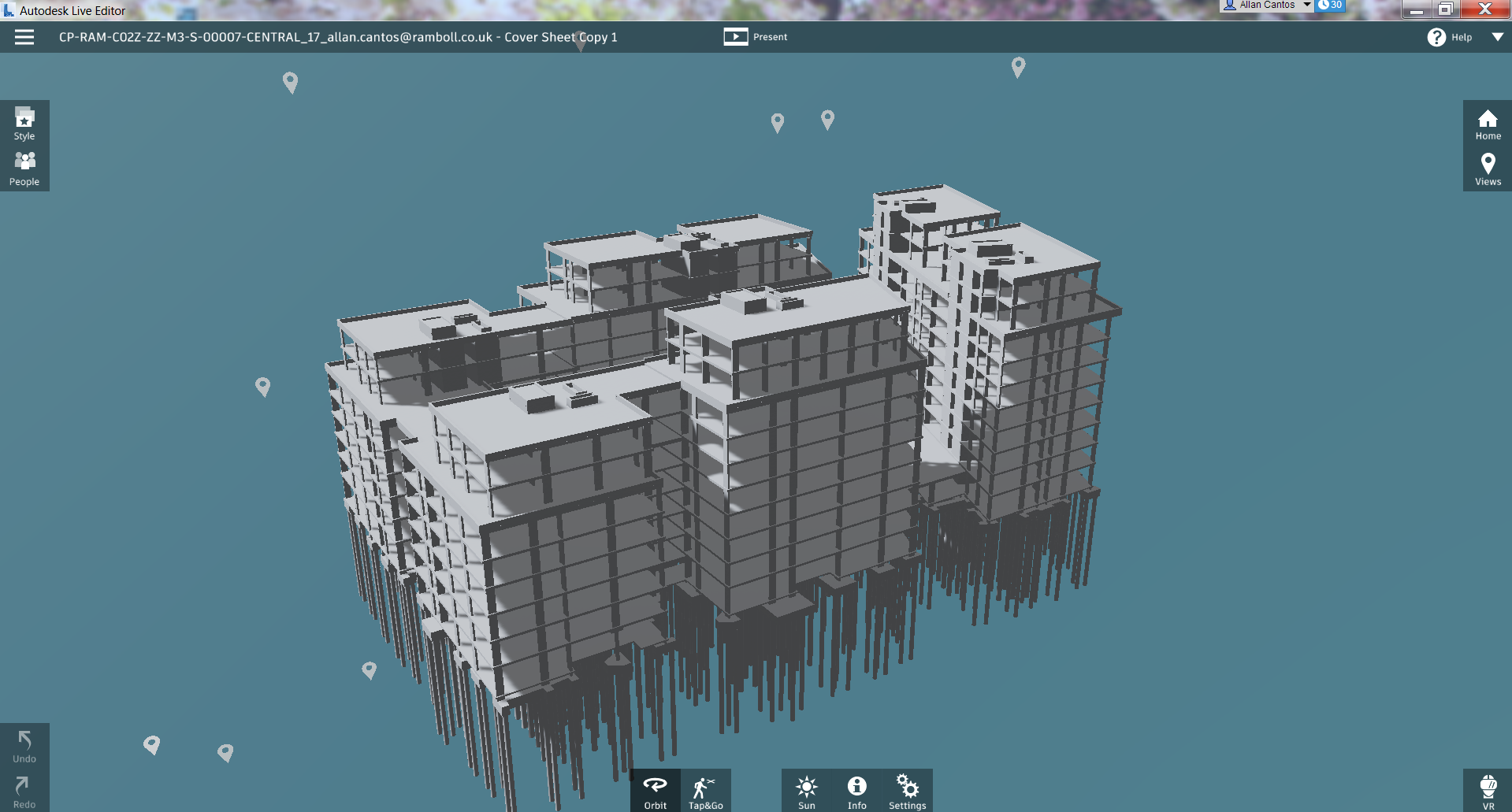
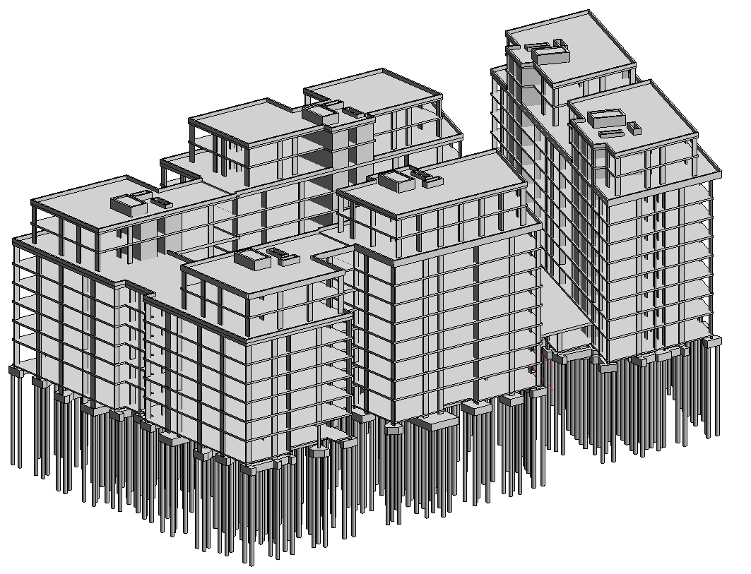
Here is the view we want to appear on the “Sheet Model” that he fixed at the “Sports Hall” Revit model.

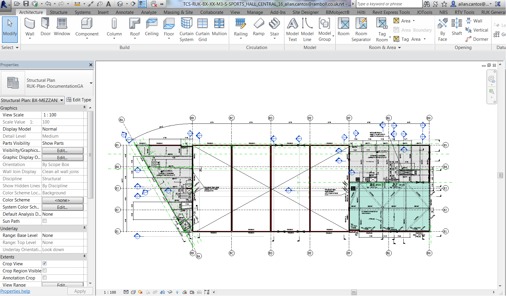
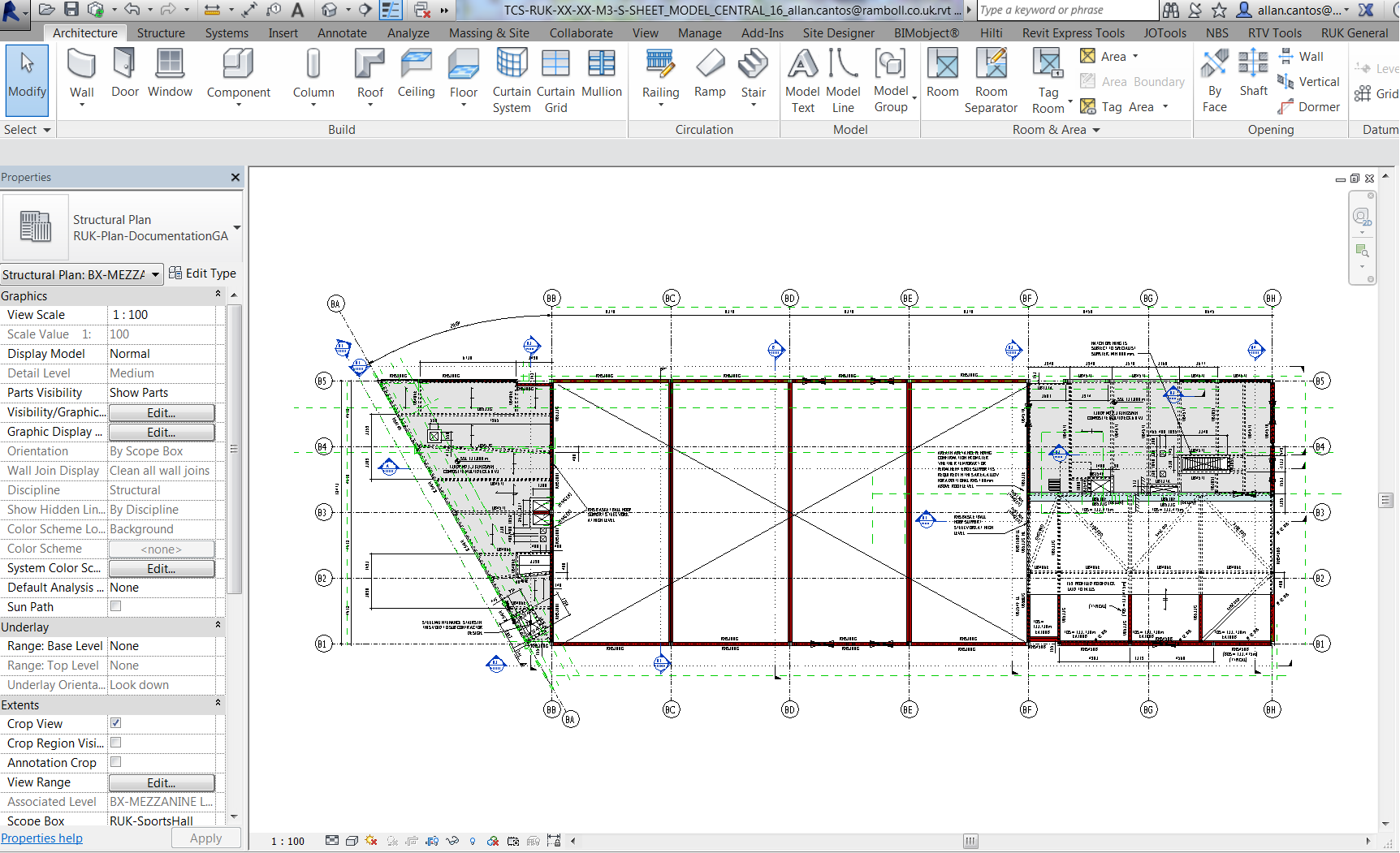
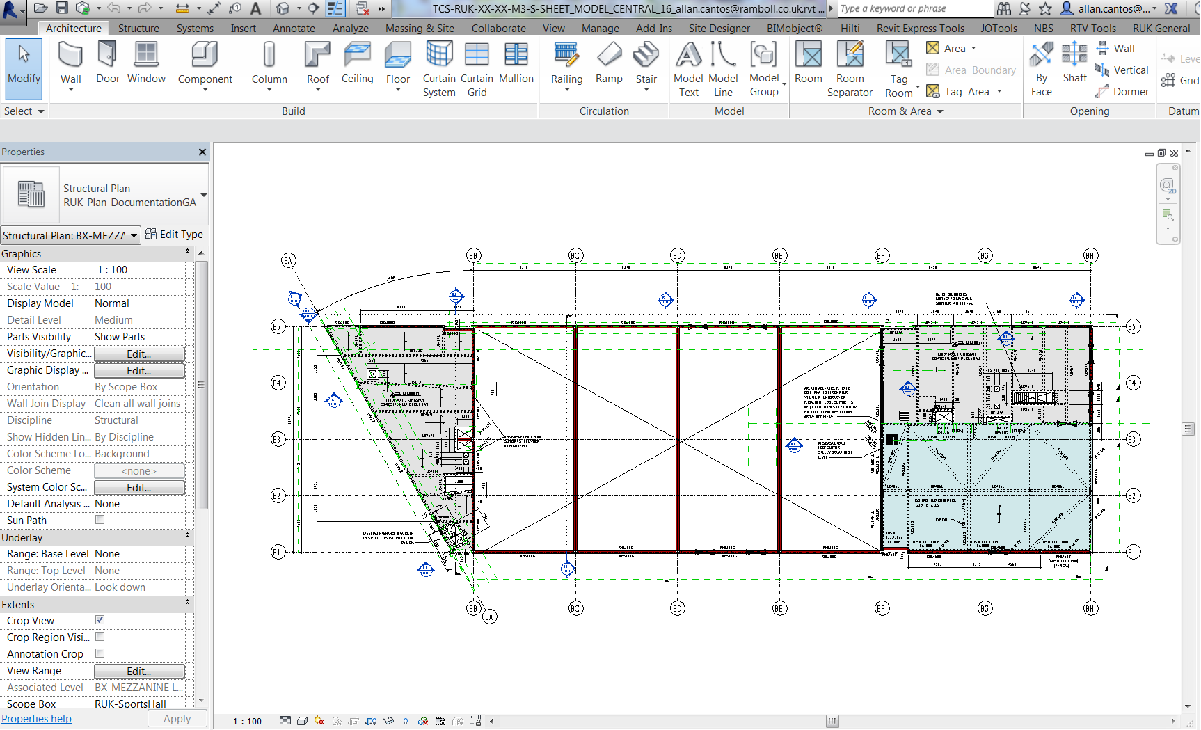
And here it is when you are on the “Sheet Model”. The “green area” on the lower right-hand corner seems missing or might be a view range issue.

He looked at “View Range” and made it sure that the settings he has in “Sheet Model” Revit model matches the one he has in “Sports Hall” Revit model and both were the same.

So what could be the problem why the views are not the same considering that both models are now using the same “View Range” values?

Ok, here is the solution. If this view can’t be fixed by adjusting the “View Range” from the “Host View” (Sheet Model Revit model view range settings), then I will use the “Linked View” (Sports Hall Revit model view range settings) instead.

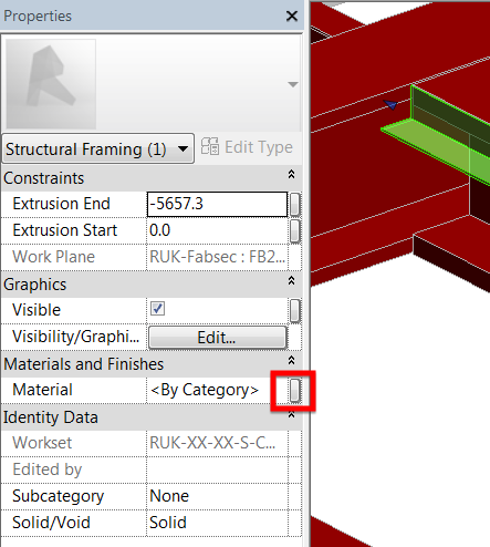
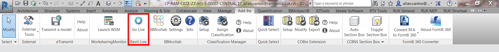
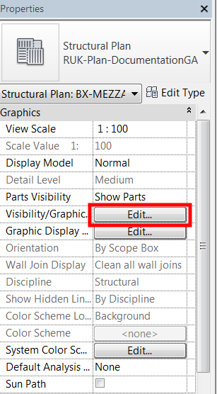
I started looking at the “Visibility Graphics” by clicking “Edit” or type “VG” on your keyboard.

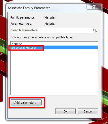
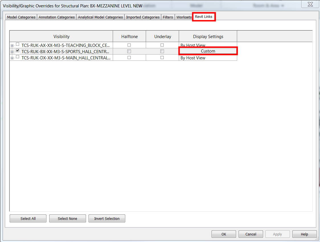
Then go to the “Revit Links” tab and click on “Custom”

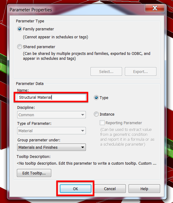
Look for the “View Range” and instead of “By host view”, select “By linked view”


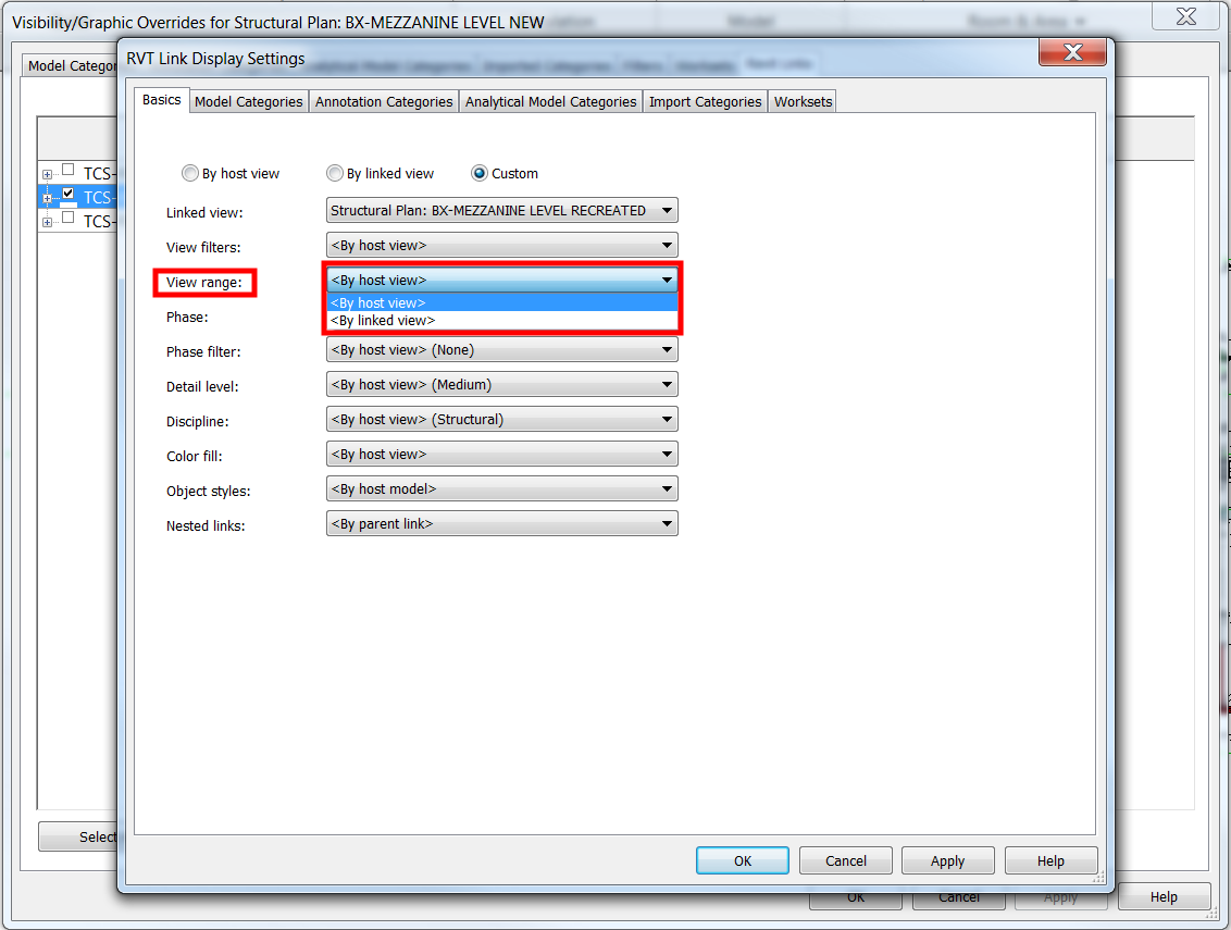
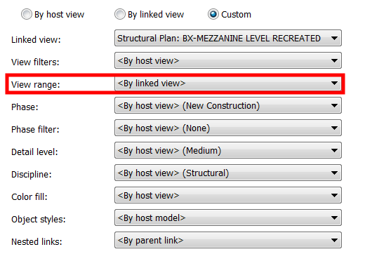
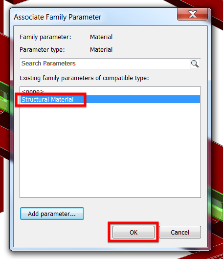
Click “Apply” then “OK” and another “OK” and voila! Our view is now fixed!

Here is the view that my colleague wants to achieve on his “Sheet Model” Revit model.

I hope you’ll find this trick useful. If you think I can be of help on your project, don’t hesitate to drop me an email on my “Contacts” section. I welcome your feedback, comments, questions, corrections and additional information relating to this article. If you know a better way, please leave your comment; by all means, let me know. Thanks.

Have a great day!

Cheers,

Allan Cantos

Revit Extension Part 1 – Content Generator

Hello there. I trust you are having a great day. Yesterday, a colleague of mine in the office reminded me about one of the Revit Extension tools that are useful when creating your own families. I’m talking about “Content Generator” Revit Extension Tool.

I’ll run you on how this Revit Extension tool works. For today’s demonstration, let me create a custom angle section shown below.

Normally, when creating a custom section like the one shown above, some technicians and that includes me, do not use “Content Generator” Revit Extension Tool but rather use “Model In-Place”. Though I used this before but honestly I have forgotten about it.

The problem with modeling an in-place family is that you can’t add them to your schedules.

Let us have a look, for instance, this beam where I’ll attach a custom 140×150 angle, 10mm thick as shown.

Let me re-create this in-place family. First, click on “Model In-Place”

Next, set the “Family Category and Parameters” to “Structural Framing” and click on “OK”

Assign a name for the custom family. I’ll call it 140x150x10 custom angle

Make sure that I am on the right work plane. I’ll go ahead and click on “Set”

Next I’ll pick a plane

Then I’ll pick the plane at the end of the beam shown


Next, go to “Forms” panel tab and select “Extrusion”. This will bring me to sketch mode.

Go ahead and sketch the angle profile using any appropriate “Draw” panel icons.

Click the green check icon shown once the profile is completed

Next, drag the one of the end of the extrusion shape handle to the opposite direction

And you should have something like this

Continue dragging the extrusion shape handle until I reach the desired length of the custom element.

Next, I’ll assign a material by clicking the icon shown below

Assuming I do not have the “Structural Material” as my existing family parameters, to create one, click on “Add parameter”

Call it “Structural Material” and click “OK”

Next, select “the newly created parameter which is “Structural Material” and click “OK”.

At this point, I am now ready to accept the changes by clicking on “Finish Model” and click anywhere on the working area to deselect the element.

And click on “Finish Model”

By selecting again the newly created custom angle element, you can now assign a material on it.

Now here is the problem, if I look at the properties of this element by clicking on “Edit Type”, I don’t see any useful information such as the size and weight and therefore, if I have lots of model in-place on my model and I want to get the building tonnage, I will have the wrong calculated value because these elements will not be part of the calculation.

To fix this, creating a custom family using “Content Generator” Revit Extension tool will come into handy. To create one, on your “Menu” options, look for “Extensions”

Go to “Tools” and select “Content Generator” from the drop-down list.

Go to “File” menu and select “Regional settings”

Select the location, in my case “UK” and click “OK”

Go to “Parametric section” and click “Add”.

I am creating a custom framing element and therefore under “Element Types” I only selected “Framings”.

Follow the settings below

Click “OK” and I will have the information shown below

Update the dimensions and click “OK”

The newly created custom framing family is now available to use.

And let’s have a look at the properties. You can rename the family to suit your needs.

Now I can get something useful and it is parametric. I’ll change the sizes to check if the “Structural” parameter information will update.

Ops…. It did not. Let me edit the family to investigate why it did not update automatically after changing the dimensions to a new size by clicking on “Edit Family”

However, it’s not a problem. For instance, the weight “W”, you can add formula to calculate the weight based on the dimensions given or you may add a “Volume” parameter then use this value to calculate the weight. I’ll leave it to you to update the structural parameters to suit your needs and that should be it.

Next time I’ll tell you how to install Revit Extensions on Revit 2017.

Have a great day.

Cheers,

Allan

My Autodesk Revit Live Experience

Today I’ll talk about my Autodesk Go-Live experience from installation to uploading my Revit model.

For more information, please visit the Autodesk website at https://www.autodesk.com/products/revit-live/overview

Out of my curiosity, I decided to document the process of bringing my Revit model to Autodesk Go Live. So let’s begin.

I started by visiting the link I provided above and signed in using my Autodesk account. If you haven’t got one, you’re free to create one by clicking on the “Create Account” button.

Type in my username

Type in my password

And I can begin to download the 30 days free trial of Autodesk Revit Live by clicking on the “Begin Download” button.

Next is to read the terms and conditions that will pop up on the screen

I’m happy with all that is written, as if I have any other choice, tick the box required and click on “Continue”

The setup file is now downloading and once done, I’ll click on the downloaded file on the lower left-hand corner and select “Run” to start the installation.

You may need to ask your IT to have it installed on your machine if you do not have admin rights.


Just click “Yes”

Next is to click “Install” to begin the installation

Tick the “Accept” button after reading the “License and Services Agreement” and click “Next”. No other choice than to accept it anyway if I want it to be installed on my machine.

Since I have it installed already previously, I’ll cancel the installation. However, click on the “Install” button to continue with the installation process if you don’t have it installed yet on your machine.

Once the installation is finished, I can see a new plugin on my “Add-ins” menu options called “Revit Live” on my Revit panels tab.

Here is the Revit model I would like to upload on Autodesk Live.

Click on “Go Live” button under “Revit Live” panel.

Revit Go Live will try to list down any problem with the model, it will be listed here if I have some. I have to fix those problems first before moving on to the next step. In this example, I’ve got a “Visual Style” warning only and therefore I can carry on sending my structural model to Revit Go Live. Now click on “Save and Go”.

Good to see that is it working. Uploading begins…

The Revit Live service is preparing my model to be available to view in Revit Live.

The model is being sent back to me under .lvmd file extension

I received a confirmation email of what to do next once the file is downloaded on my machine.

Now I am ready to open my .lvmd file to “Autodesk Live Editor”.

This window will pop up, just click on the “x” button on the upper right-hand corner.

Autodesk Live Editor is now loading.

Now we are at the “Project Area” where all previous file you worked on will appear here. To open that .lvmd file, you can click on “Select file” or just drag and drop on the box I highlighted in “Red”.

Importing Step 1 of 2

Importing Step 2 of 2

The file is now in Autodesk Live. Happy to see its working.

Video link for Autodesk Go Live test on my structural model:

And here is the link with Architectural model attached. I realized that architectural walls were missing from the Architectural Revit model, I made a wrong choice of sample model, nevertheless, I’m happy that it works.

Thanks for dropping by.

Cheers,

Allan Cantos

Positive SSL