Hello there. I trust you are having a great day. Yesterday, a colleague of mine in the office reminded me about one of the Revit Extension tools that are useful when creating your own families. I’m talking about “Content Generator” Revit Extension Tool.
I’ll run you on how this Revit Extension tool works. For today’s demonstration, let me create a custom angle section shown below.
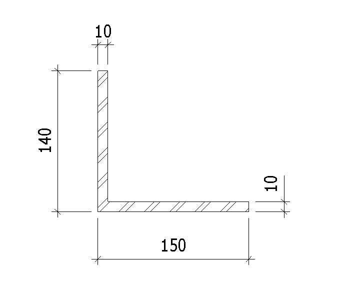
Normally, when creating a custom section like the one shown above, some technicians and that includes me, do not use “Content Generator” Revit Extension Tool but rather use “Model In-Place”. Though I used this before but honestly I have forgotten about it.
The problem with modeling an in-place family is that you can’t add them to your schedules.
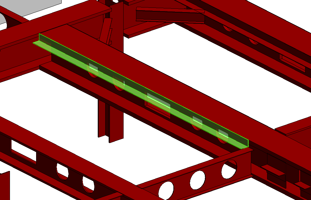
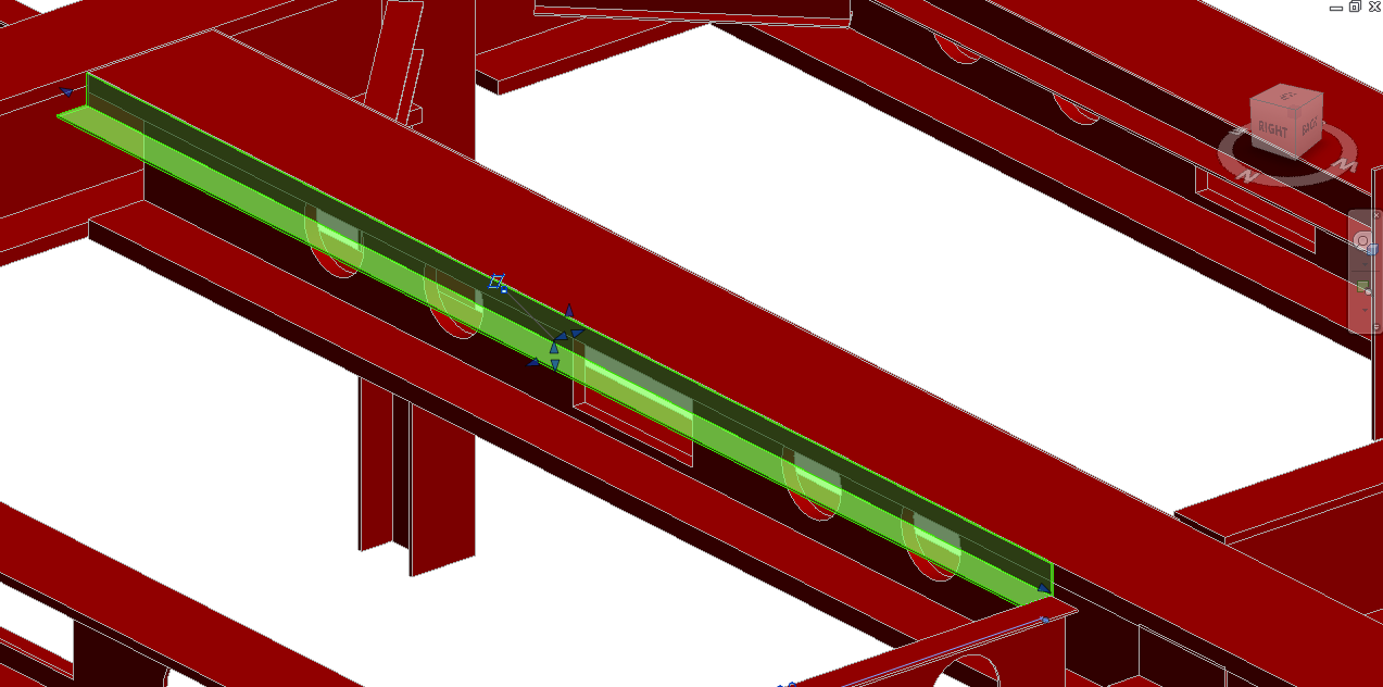
Let us have a look, for instance, this beam where I’ll attach a custom 140×150 angle, 10mm thick as shown.
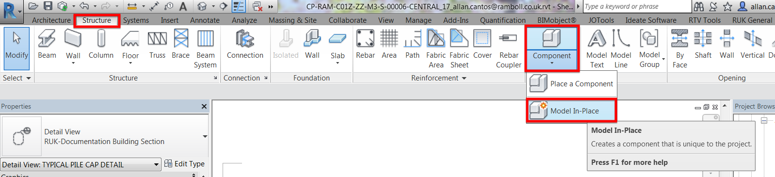
Let me re-create this in-place family. First, click on “Model In-Place”
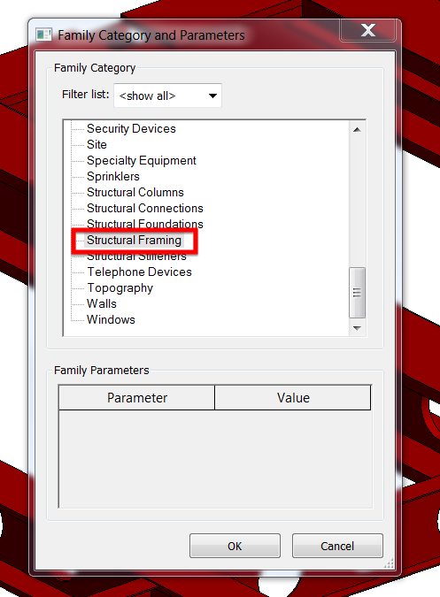
Next, set the “Family Category and Parameters” to “Structural Framing” and click on “OK”
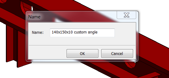
Assign a name for the custom family. I’ll call it 140x150x10 custom angle
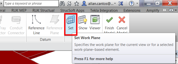
Make sure that I am on the right work plane. I’ll go ahead and click on “Set”
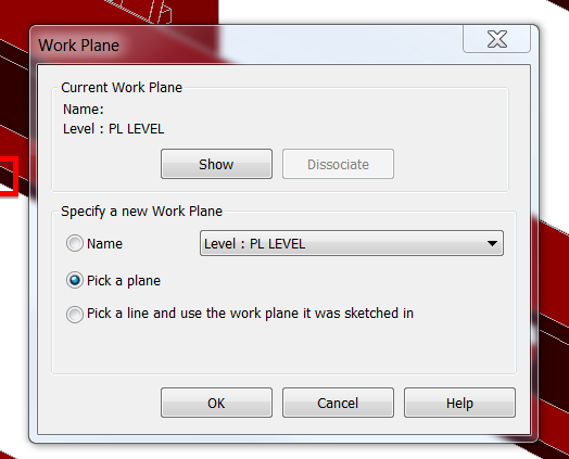
Next I’ll pick a plane
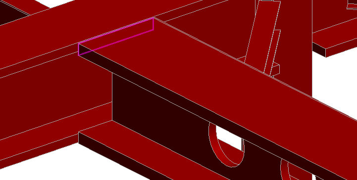
Then I’ll pick the plane at the end of the beam shown
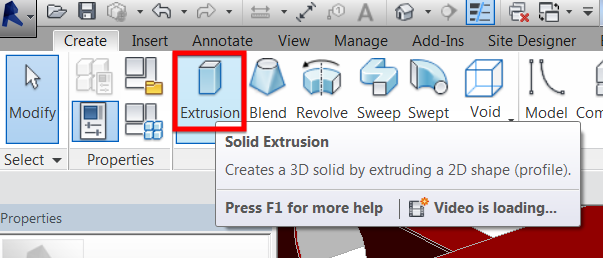
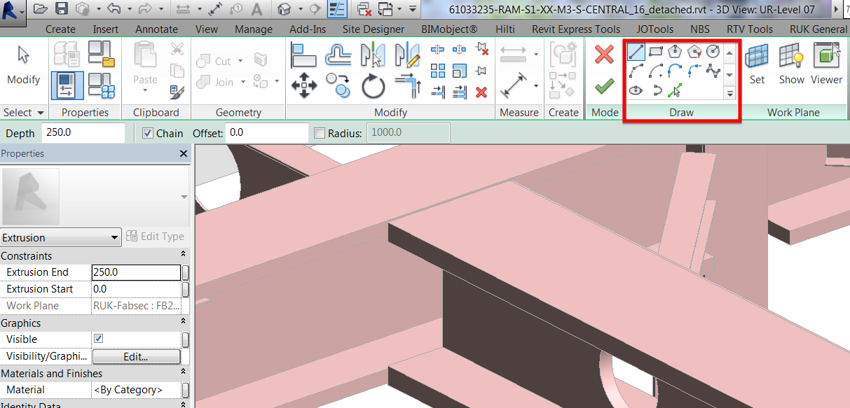
Next, go to “Forms” panel tab and select “Extrusion”. This will bring me to sketch mode.
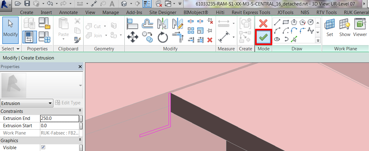
Go ahead and sketch the angle profile using any appropriate “Draw” panel icons.
Click the green check icon shown once the profile is completed
Next, drag the one of the end of the extrusion shape handle to the opposite direction
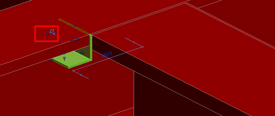
And you should have something like this
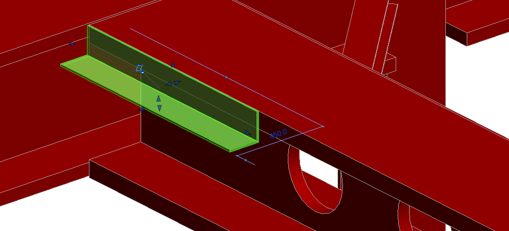
Continue dragging the extrusion shape handle until I reach the desired length of the custom element.
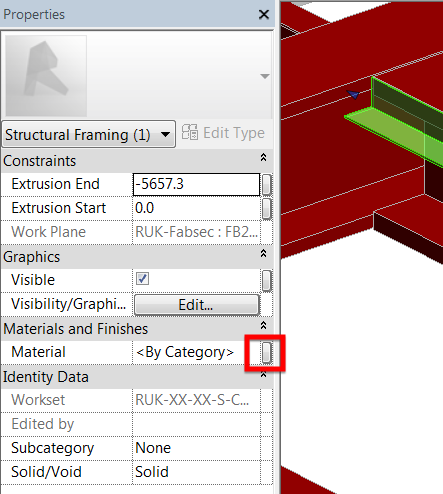
Next, I’ll assign a material by clicking the icon shown below
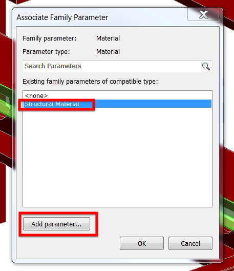
Assuming I do not have the “Structural Material” as my existing family parameters, to create one, click on “Add parameter”
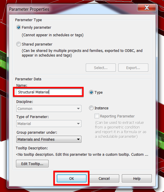
Call it “Structural Material” and click “OK”
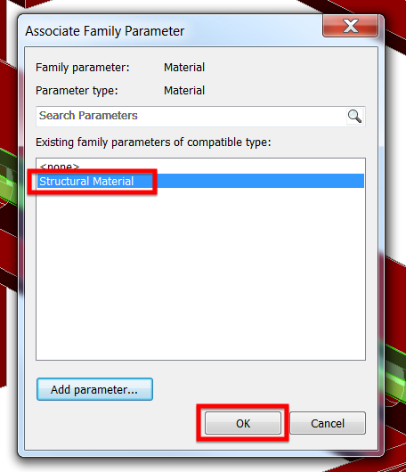
Next, select “the newly created parameter which is “Structural Material” and click “OK”.
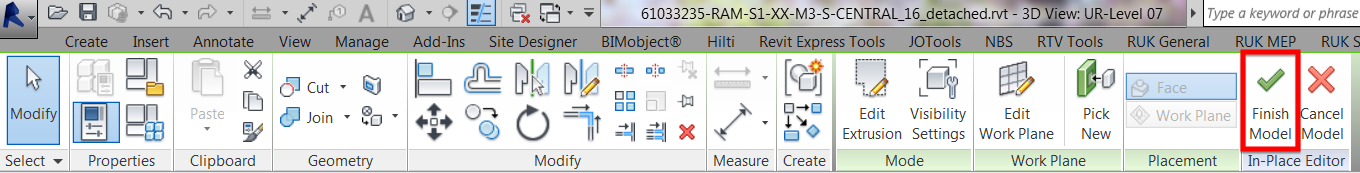
At this point, I am now ready to accept the changes by clicking on “Finish Model” and click anywhere on the working area to deselect the element.
And click on “Finish Model”
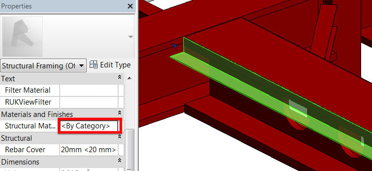
By selecting again the newly created custom angle element, you can now assign a material on it.
Now here is the problem, if I look at the properties of this element by clicking on “Edit Type”, I don’t see any useful information such as the size and weight and therefore, if I have lots of model in-place on my model and I want to get the building tonnage, I will have the wrong calculated value because these elements will not be part of the calculation.
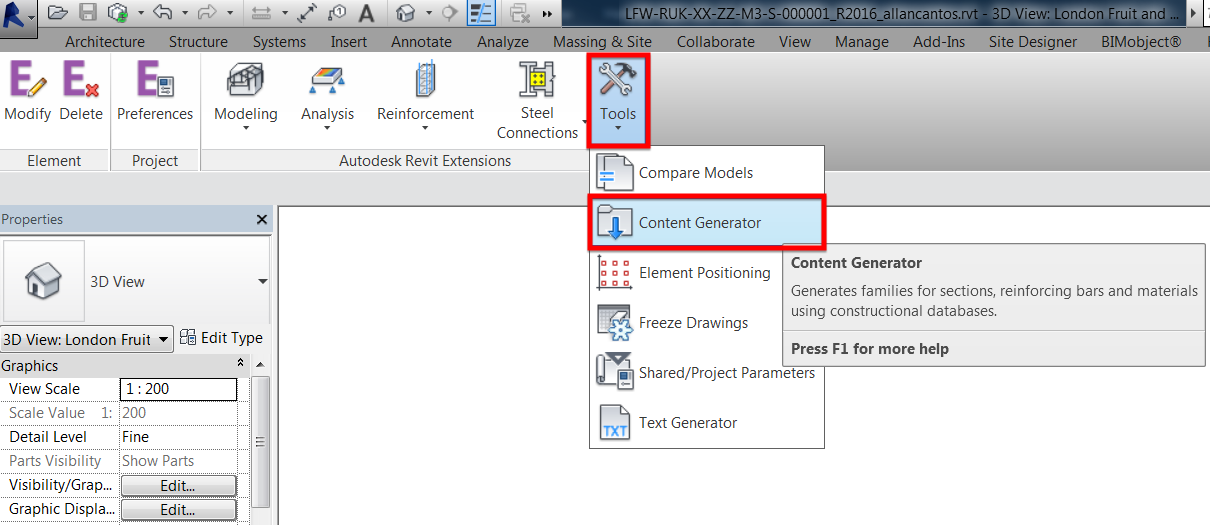
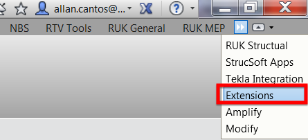
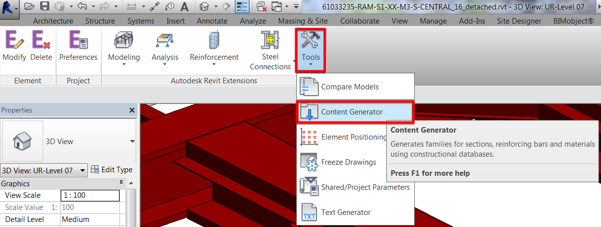
To fix this, creating a custom family using “Content Generator” Revit Extension tool will come into handy. To create one, on your “Menu” options, look for “Extensions”
Go to “Tools” and select “Content Generator” from the drop-down list.
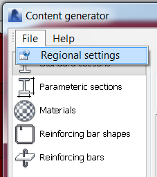
Go to “File” menu and select “Regional settings”
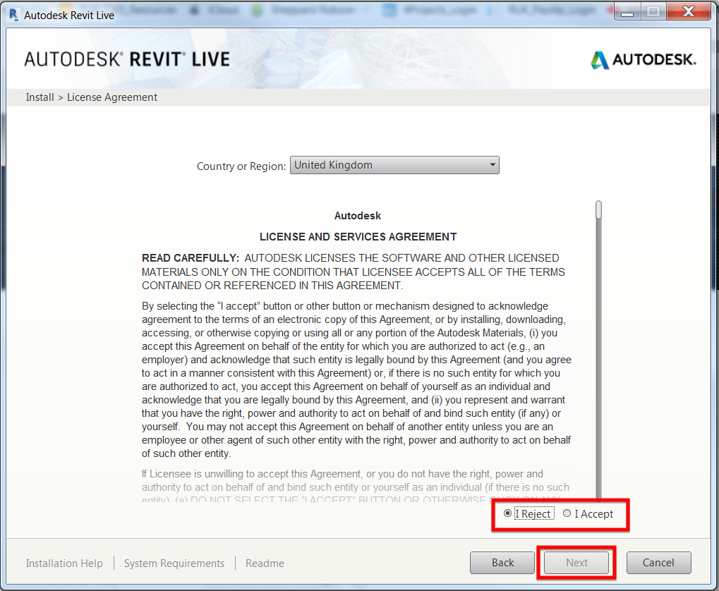
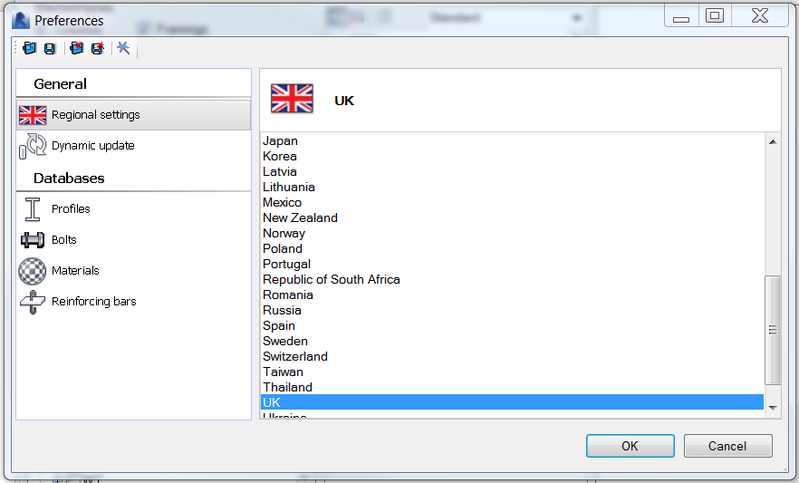
Select the location, in my case “UK” and click “OK”
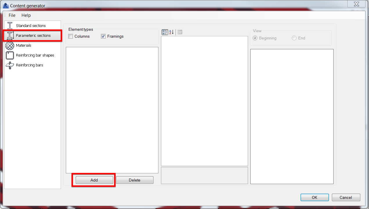
Go to “Parametric section” and click “Add”.
I am creating a custom framing element and therefore under “Element Types” I only selected “Framings”.
Follow the settings below
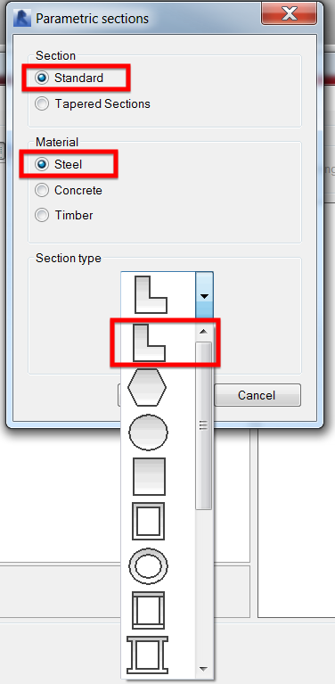
Click “OK” and I will have the information shown below
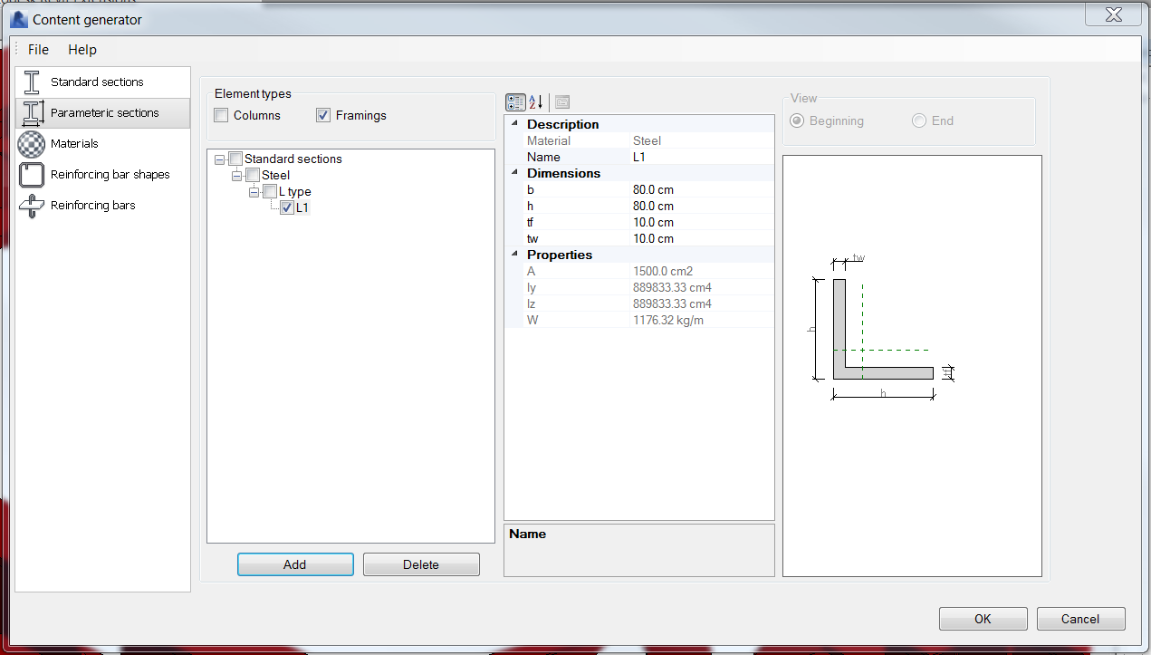
Update the dimensions and click “OK”
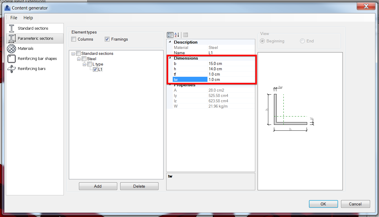
The newly created custom framing family is now available to use.
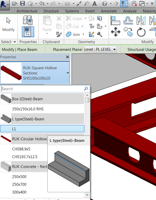
And let’s have a look at the properties. You can rename the family to suit your needs.
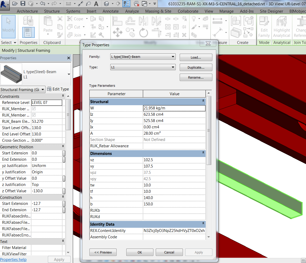
Now I can get something useful and it is parametric. I’ll change the sizes to check if the “Structural” parameter information will update.
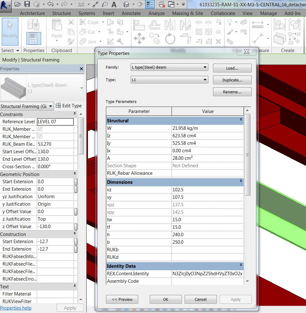
Ops…. It did not. Let me edit the family to investigate why it did not update automatically after changing the dimensions to a new size by clicking on “Edit Family”
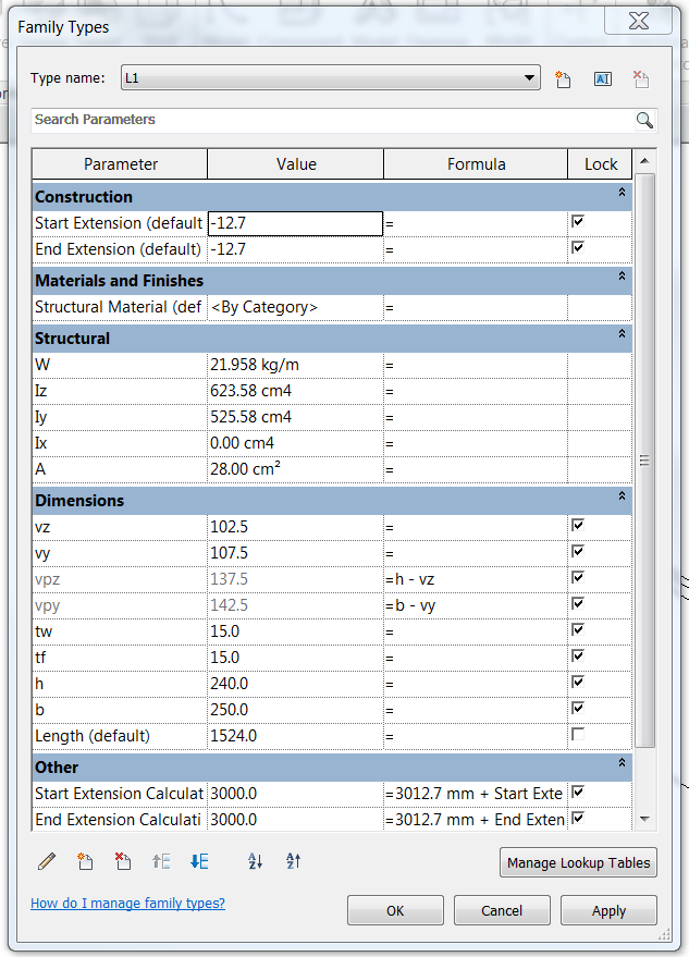
However, it’s not a problem. For instance, the weight “W”, you can add formula to calculate the weight based on the dimensions given or you may add a “Volume” parameter then use this value to calculate the weight. I’ll leave it to you to update the structural parameters to suit your needs and that should be it.
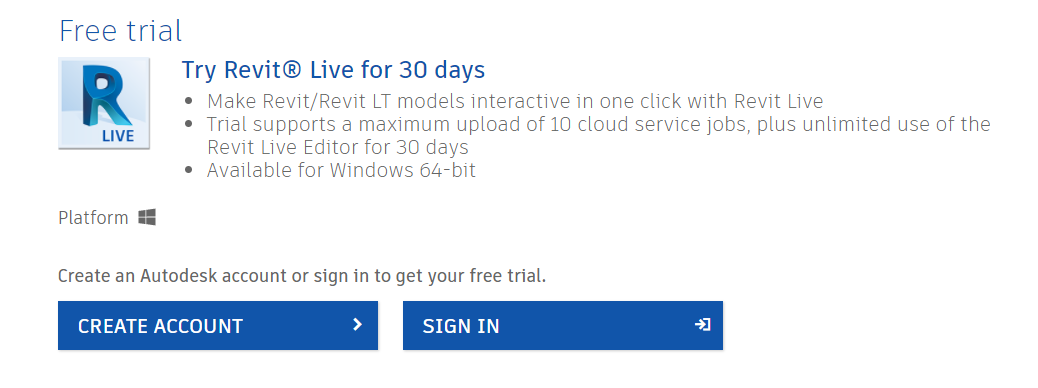
Next time I’ll tell you how to install Revit Extensions on Revit 2017.
Have a great day.
Cheers,
Allan