How to view missing architectural 2D detail line furniture in Revit.

Hi there, I hope you are well.

Apologies for not being able to write something in the past few weeks for being to occupied with lots of things.

Without further a do, here is my scenario. I need to update the extents of my area loading plan hatches, however, upon reloading the latest architectural model (Building F), all I can see are the partition walls and doors and without the furniture. I have 2 building side by side, Building E and Building F. On the adjacent building, Building E, I can see the furniture.

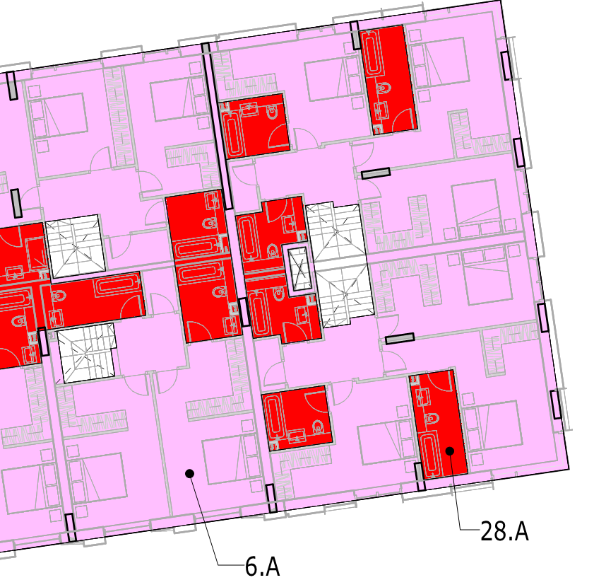
You can see from the image below that it will require some updates. It would be very helpful if you can see the furniture for you to know where exactly the bathroom (hatched in red) are located, for instance.

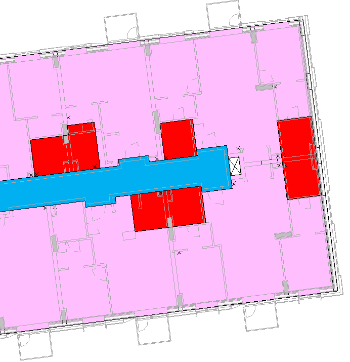
I opened the architect Revit model to check if they have the furniture layout, and yes, they have it in their model under a separate workset.

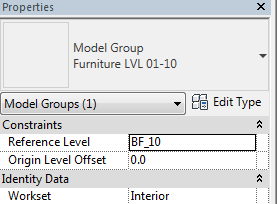
I checked my “View Template” view properties one by one and all looks good to me.

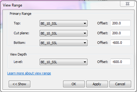
I checked the “View Range” and it also looks fine to me.

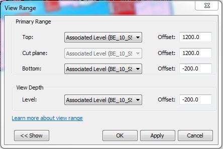
If you’re wondering why I set my “View Depth” to just 200 below my associated level is because I don’t want to see the partition walls below. All I wanted to see are the partition walls on the floor I’m looking at.

If I set the “View Depth” way below the slab soffit, say -1200, the result is, you’ll be able to see the wall partitions from the level below (making the floor plan looks complicated).

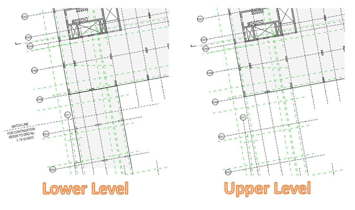
Now, I remember something and that is, for instance at Level 10, Level 10 of Building E is not the same as the Level 10 of Building F. My “View Range” associated level is from Building E. Building F Level 10 is below Building E Level 10 by 575mm.

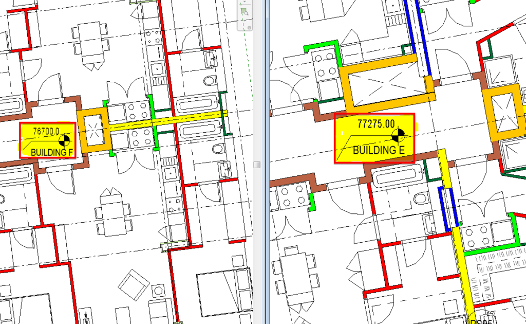
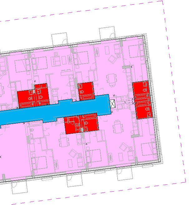
So, in order for me to see the furniture from Building F, I need to add a plan region (hidden line in magenta from the image below) in order for me to set a view range specific to Building F.

For some of you who are not familiar with “Plan Region”, I’ve written an article about this topic which you can find from visiting the link below:

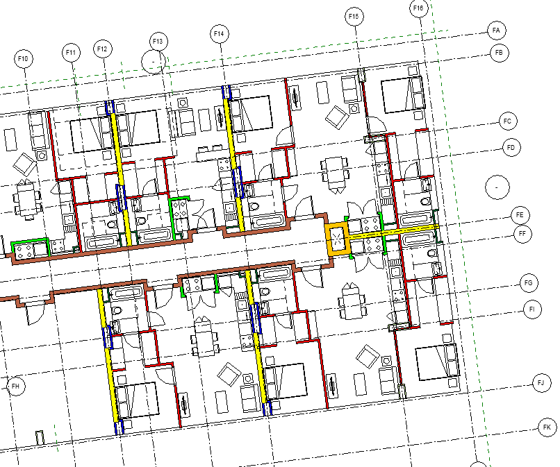
After adding the “Plan Region”, I can now set my “View Depth” making it sure that my depth is within the thickness of my concrete slab floor (225mm thick concrete slab).

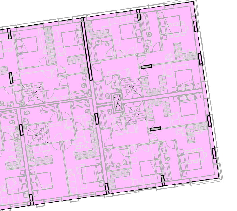
Click “Apply” and “Ok”. I should now be able to see my furniture layout.

For beginners in Revit, I hope you find this helpful.

Cheers,

Allan Cantos

BSc. Civil Engineering / Principal Structural Technician

Revit Idea 02

Hi there! I hope you are well.

There is a great discussion here about one of my Revit Idea posts.

Check it out here and VOTE for it if you want it to happen in the future release of Revit software.

Grid Lines: Having the ability to control the top constraintsh

Have a great day.

Cheers,

Allan Cantos

BSc. Civil Engineering / Principal Structural Technician

Loading Schedule form Spreadsheet to Revit: How do you normally do it?

Hi there, Allan here form Allscan12. I trust you are all well.

Recently, I came across one project in Revit 2017 where the technician was having the trouble of how to update/fix the loading schedule already on the Revit sheet.

Here is how the schedule looks like before updating:

Basically, it consists of a schedule and some coloured hatching done as a Legend. The update to be done is adding two more rows; LP10 and LL05.

We do have a third party plugin in the company called BIMLink from Ideate Software company where we can export the spreadsheet, update the values in Excel, and import back the values to our Revit schedules, which really works well.

Let’s take a look at one of the loading key and what are the available parameters.

For whatever reason, you have the parameters but there are no values assigned, however in the schedule, you have the complete information needed.

Normally, if we have the loading plan from the spreadsheet, we link it in AutoCAD then link this DWG to the Revit and we’re done. We have created quickly the loading schedule. However, the downside is, any time you made changes to the spreadsheet you would have to open AutoCAD and re-save it with the update, and then reload the AutoCAD linked in Revit. Sometimes you may need to rebuild the table in AutoCAD if there are lots of changes happened. Another downside is, not all know how to operate AutoCAD. They have to call someone to help/teach them how to do it if that will be their first time to do this method. This is not a great workflow but works well.

I’m intrigued by how this loading schedule was done in this project.

Clearly, upon my investigation, no values have been assigned to the parameters for the ‘Detail Item Filled Region’. So how was this schedule created?

I’ll tell you the secret.

Some of us don’t bother about other options available when creating the schedule. When you right click under ‘Project Browser/Schedules/Quantities’, and select ‘New Schedule/Quantities…’, you’ll have the option to select from the list of categories available.

Since this hatching was done using ‘Detail Items/Filled Region’, let’s create a new schedule under ‘Detail items’ category and the TRICK now is to make sure to select ‘Schedule keys‘. This trick is very useful if you have a table that you would like to add quickly to your sheets.

Then you can start adding the parameters according to the number of columns you needed.

Then followed by adding rows where you’ll be adding the information

Here is that loading plan where I’ve added two rows for LP10 and LL05.

The rest is for you the tidy up the schedule under the ‘Sorting/Grouping, ‘Formatting’ and ‘Appearance’ tab of the schedule properties.

Have you done some schedule in different method? Please share and let’s spread the knowledge.

Have a great day and have a happy weekend.

Cheers.

Positive SSL