Revit voids not exported to IFC

Hello there. I trust you are well.

We regularly export our Revit model to IFC, together with native RVT and NWC models, as part of forthnightly model exchange. Recently I was told that some of the voids were not being converted to IFC. I was surprised why it happened, so I made some investigations.

The issue of converting the Revit model to IFC is that IFC is not treating the other Revit openings as slab openings as you can see here:

though they are all modelled the same, as shaft openings

Then I did a test of tracing the slab edges around the openings which I shouldn’t be doing as it creates a lot of work should the riser opening changes its size, but I did just to do this test and it looks ok.
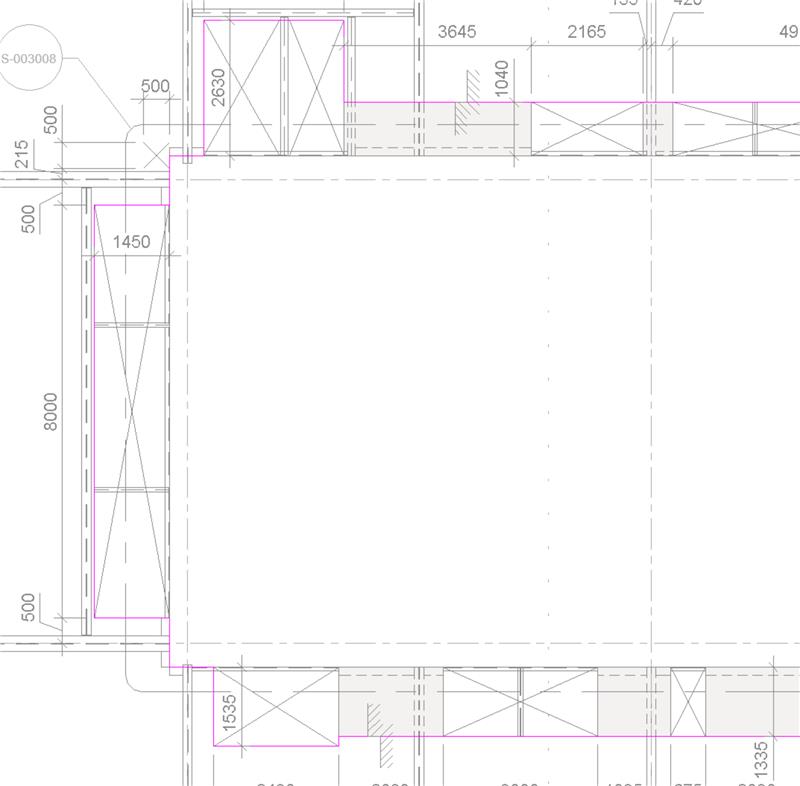
Then I tried to trace the slab edge to the face of the core walls to check if those voids will exist once converted to IFC, all the voids did not get converted properly except one for some reason.

Then I did creating a detached copy of the model, though I shouldn’t be doing it, but for the purpose of testing I did. The result is the same as if we are exporting the IFC from the live model.

So there is something about how IFC is converting the voids.

Did you come accross this problem before? Would you mind sharing in the comments below how you solve it, please? I appreciate your contribution and thank you in advance.

Have a lovely day! Cheers.

Create Structural Beam Penetration – 3 Options

Hello there. I trust you are well.

Have you ever wonder how to create voids on your structural framing family? Please check my YouTube video (link provided below) explaining 3 options on how you can create voids on your structural framing elements.

Actually, there is a fourth method where you embed the voids within the family, but the issue with this methos is when you load a new type, they will be overwritten and disappear unless you create a new type within your structural framing company library specific with structural framing with voids.

I hope you find this useful.

Have a great day.

Cheers!

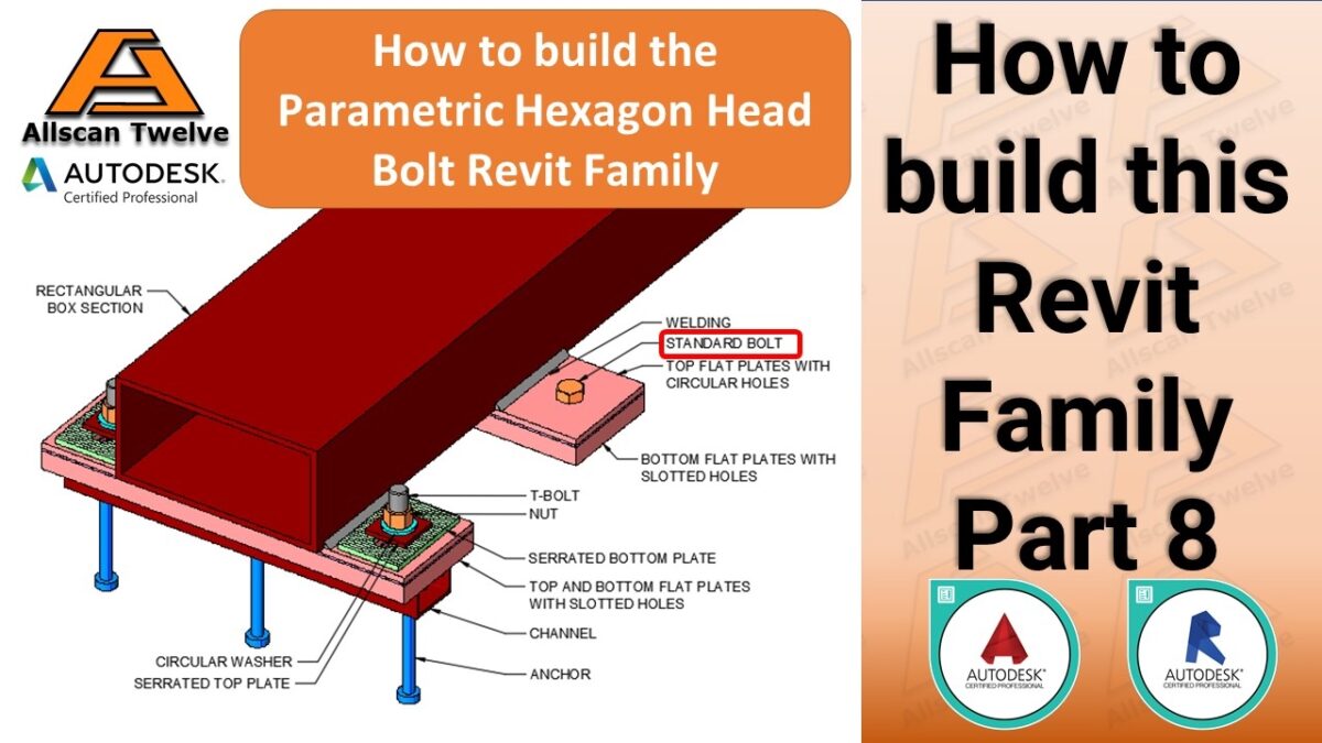
How to build a Revit Family – Part 8 / How to create a hexagon head bolt Revit Family

What’s up, guys? Allan Cantos here and for the 8th part of this video series, I’ll show you how to create the parametric hexagon head bolt Revit family.

Here is the link to part 1: How to create a parametric channel with anchors https://youtu.be/ieKGfNmyUSc

Here is the link to part 2: How to create a parametric slotted void Revit family https://youtu.be/CFWJKYZQQ6M

Here is the link to part 3: How to create the flat plate with slotted holes Revit family https://youtu.be/nP33rJhYk_Q

Here is the link to part 4: How to create the serrated bottom plate with slotted holes Revit family https://youtu.be/lbaXxKLh8Wg

Here is the link to part 5: How to create the parametric serrated top plate with a circular void Revit Family. https://youtu.be/JG_P_zhtIBU Here is the link to the T-Bolt head profile in the AutoCAD file. https://www.dropbox.com/s/w54uc9quexxbrmg/T-Bolt_Head_Profile.dwg?dl=0

Here is the link to part 6: How to create the parametric T-bolt Revit Family. https://youtu.be/kxj0BrLjLYU

Here is the link to part 7: How to build the parametric Bolt Nut Revit Family. https://youtu.be/yOQdeJM20to

Kindly support my YouTube channel by smashing that thumbs up button, subscribing and turning on the notifications so that you don’t miss out on my new videos.

Subscribing to my YouTube channel won’t cost you anything but, by subscribing, you are helping me grow my YouTube Channel. Thank you in advance and for your support. Please do consider leaving a comment and share this video with your colleague who is starting to learn how to build a Revit Family.

Sharing is caring. Thanks for watching!

Have a great day!

Cheers!

Positive SSL