In this article, we are going to look at Revit’s “Plan Region” tool. This is for beginners, however some experienced technicians still don’t know or haven’t used this tool since they have started using Revit and may have forgotten about it. I ‘ve created this article to share with people who may have questions about how to deal with a view range problem with which the “Plan Region” tool could be an answer. This is one of the Revit tools under the “View” menu options and “Create Panel” Tab which can be useful if you know how to use it. I’ll demonstrate the type of problem that the “Plan Region” tool was created to solve.

For instance, we’ll use one of the projects that I’m working on. There are two buildings, side by side, that are of different structural slab level or SSL. We first set up the cutting plane with reference to the building at the right where the SSL is higher than the building on the left.
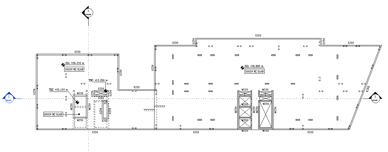
I have highlighted the yellow area shown below because I would like to have it hatched like the building on the right and the only way for me to do this is to apply a “Plan Region” on that area. So, what exactly is a “Plan Region”? Well a “Plan Region” is a small section of a plan view that has its own specific “View range” settings. Another way to think of it is a method of applying “View Range Overrides” to an area of our plan.

To add one, under “View” menu options, go to “Create” panel tab and click on “Plan Views”.

Then select “Plan Region”

Upon doing this, we are immediately put into “Sketch Mode”. Go ahead and draw a boundary around the core in question.

Trace the boundary using one of the icons under “Draw” panel tab.
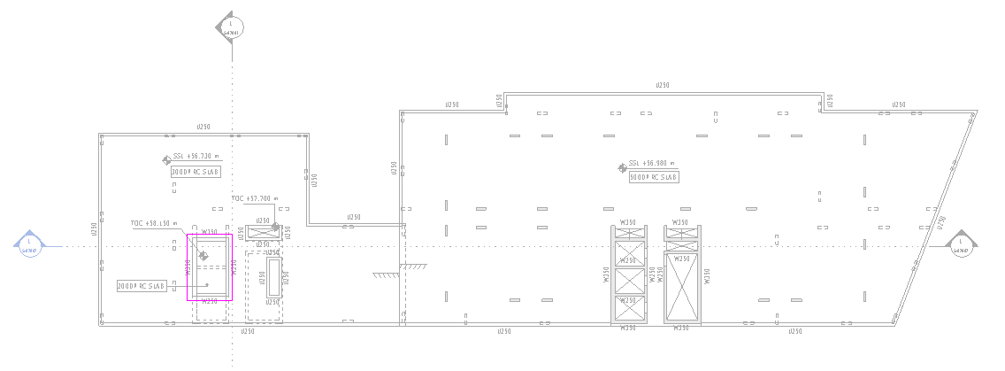
Once done, accept the traced boundary by clicking the green tick icon labelled “Finish Edit Mode”.

But still the wall isn’t hatched yet! That’s because we need to override the “View Range” by clicking on “Edit”.
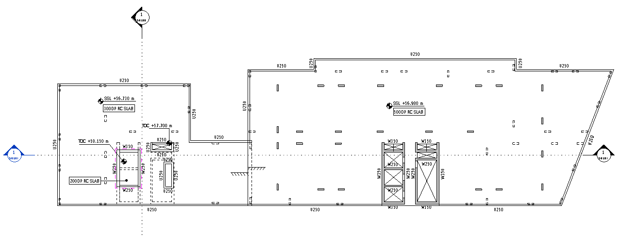

We may need to play around with the levels especially if we have set up a level for the building on the right, another level for the building on the left and another level which both buildings can use to create your plan.

Click “Apply” and “OK” to accept the changes and we should be able to see those walls hatched similar to the building on the right.
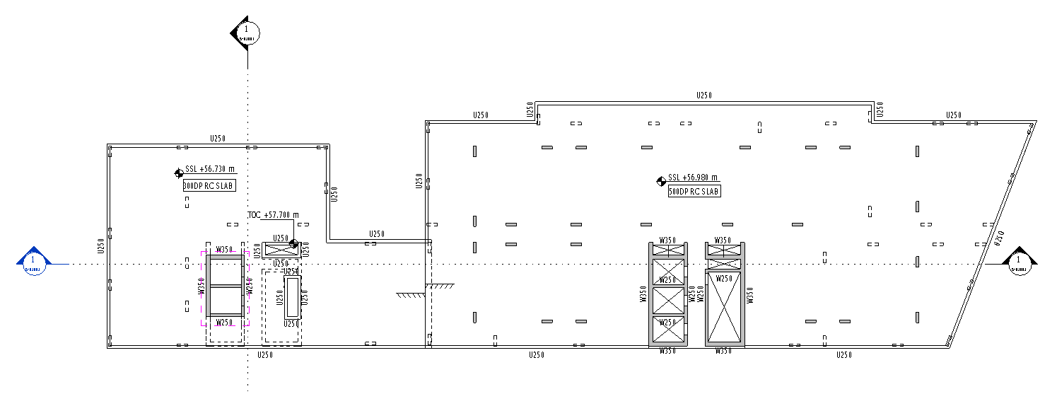
Then we go to the next floor level above and add another “Plan Region” so we’ll be able to show the Lift Overrun Structural Slab or Structural Capping Slab. We can copy the one below to make sure that it aligns on both levels.

Then we’ll paste it to the current view which will be the floor above.
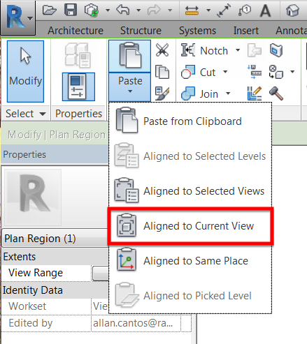
Update the “View Range” settings until you reach your desired result. A sample shown below.

By default, we will be left with a dotted magenta line showing the boundary of the “Plan Region”. If you’d prefer not to see the boundary, just uncheck the “Plan Region” under category on the “Annotation Categories” tab of the “Visibility Settings” panel.
“Visibility/Graphics” can be accessed under “View” menu options or by typing “VG” on the keyboard.

Go to “Annotation Categories” tab and uncheck “Plan Region”

Here is the section of the building running through both those buildings elevator shafts.
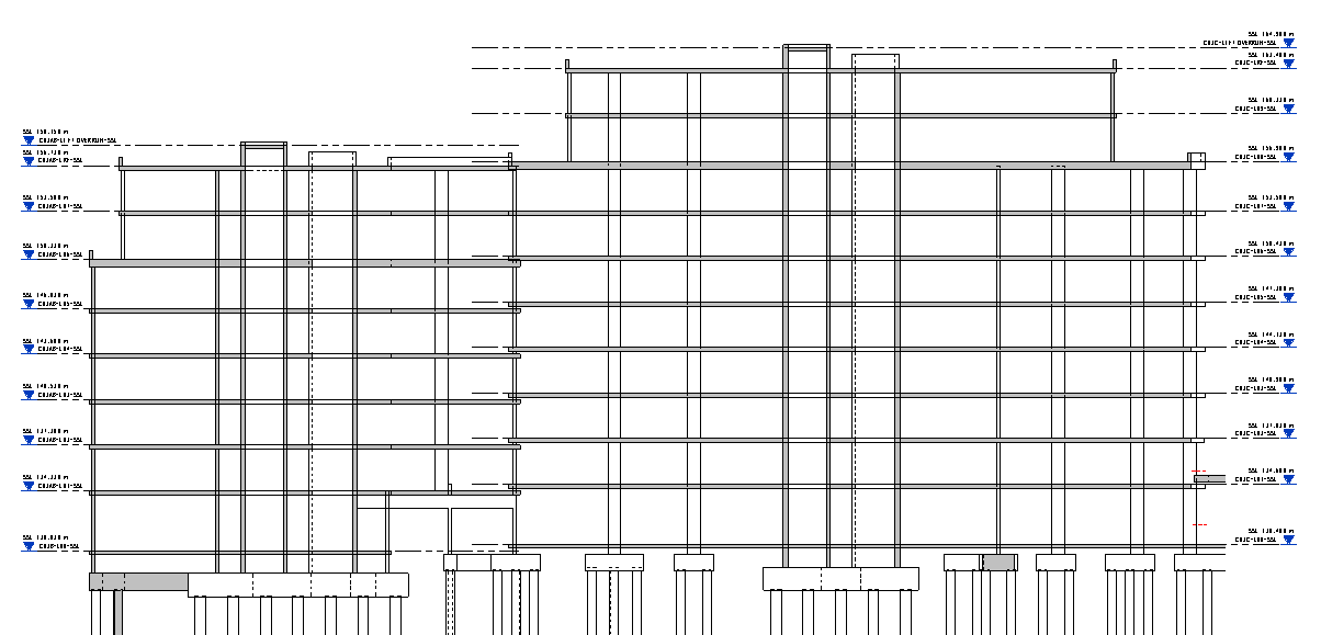
There are not as many differences in terms of levels and these can be resolved by just hiding the elements. However, some buildings have a level difference of up to 1000mm and using Plan Region will be a big help if we want to override the view range for just a specific view on the plan.
Here is another section from a different building where Plan Region can be of help to make your plan look consistent in terms of showing a hatched wall.

That should be it and thank you for dropping by.
Cheers,
Allan Cantos
